SPECTRACOOL™ Air Conditioner N28 Model INSTRUCTION MANUAL Rev.
TABLE OF CONTENTS RECEIVING THE AIR CONDITIONER.................................................................................................................................................................. 3 HANDLING AND TESTING THE AIR CONDITIONER.......................................................................................................................................... 3 HOW TO READ MODEL NUMBERS..............................................................................................
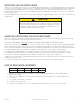
RECEIVING THE AIR CONDITIONER Inspect the air conditioner. Check for concealed damage that may have occurred during shipment. Look for dents, scratches, loose assemblies, evidence of oil, etc. Damage evident upon receipt should be noted on the freight bill. Damage should be brought to the attention of the delivering carrier -- NOT to Pentair Equipment Protection -within 15 days of delivery. Save the carton and packing material and request an inspection. Then file a claim with the delivering carrier.
TECHNICAL INFORMATION SEQUENCE OF OPERATION The air conditioner comes standard with two internally mounted thermostats or remote access control. There are two modes of operation; heating and cooling. During heating and cooling modes the evaporator fan will be running. HEATING When the enclosure temperature is below the heating thermostat setpoint, power is applied to the heaters. When the enclosure temperature is 10 degrees above the setpoint the heater is powered off.
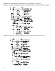
SCHEMATICS AND WIRING DIAGRAMS FOR THERMOSTAT CONTROL GENERIC 1-PHASE SCHEMATIC EXCEPT 230V 50HZ (ACTUAL UNIT OPTIONS MAY VARY) 89074302 GENERIC 230V 50HZ 1-PHASE SCHEMATIC (ACTUAL UNIT OPTIONS MAY VARY) 89074303 89074139 © 2014 Pentair Equipment Protection -5-
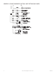
GENERIC 3-PHASE SCHEMATIC (ACTUAL UNIT OPTIONS MAY VARY) 89079267 -6- © 2014 Pentair Equipment Protection 89074139
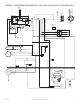
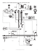
GENERIC 1-PHASE WIRE DIAGRAM EXCEPT 230V 50HZ (ACTUAL UNIT OPTIONS MAY VARY) 8 6 YEL65 6 RED30 6 3 YEL10 OR YEL65 COOLING T-STAT RED13 4 3 4 HEATING T-STAT BLU(NC) YEL(NO) 2 BLU9 1 3 MALF SWITCH (OPTIONAL) SUPPRESSOR (OPTIONAL) THERMAL DISPLAY (OPT.) 115(230) V WHT41 BLK40 TO THERMAL DISPLAY BLK14 BRN26 10 V DOOR SWITCH (OPT.
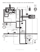
GENERIC 230V 50HZ 1-PHASE WIRE DIAGRAM (ACTUAL UNIT OPTIONS MAY VARY) YEL65 6 RED30 3 4 HEATING T-STAT BLU(NC) 1 3 MALF SWITCH (OPTIONAL) SUPPRESSOR (OPTIONAL) YEL10 OR 3 YEL65 4 COOLING T-STAT RED13 6 YEL(NO) 2 BLU9 THERMAL DISPLAY (OPT.) 115(230) V WHT41 BLK40 TO THERMAL DISPLAY BLK14 BRN26 10 V DOOR SWITCH (OPT.
GENERIC 3-PHASE WIRE DIAGRAM (ACTUAL UNIT OPTIONS MAY VARY) 89079266 89074139 © 2014 Pentair Equipment Protection -9-
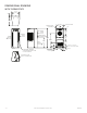
DIMENSIONAL DRAWING WITH THERMOSTATS +($7,1* 7 67$7 237,21$/ :$50 $,5 287 5(029$%/( +$1*,1* 7$%6 &22/ $,5 287 237,21$/ $&&(66 3$1(/ 21/< )25 81,76 :,7+ +($7(5 89068456 &/($1$%/( 5(86$%/( $/80,180 ,1/(7 $,5 ),/7(5 38//6 287 )5217 (1&/2685( $,5 ,1 $0%,(17 $,5 ,1 &22/,1* 7 67$7 81& 02817,1* +2/(6 $&&(66 +2/( 72 2 ' '5$,1 678% - 10 - © 2014 Pentair Equipment Protectio
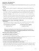
INSTALLATION INSTRUCTIONS 1. Inspect the air conditioner and verify correct functionality before mounting the air conditioner. See HANDLING AND TESTING THE AIR CONDITIONER on page 3. 2. Using the mounting gasket kit provided with the unit, install gaskets to the air conditioner, see Figure 1. 3. Mount air conditioner on enclosure taking care not to damage the mounting gasket. The mounting gasket is the seal between the air conditioner and the enclosure.
REMOTE ACCESS CONTROL (OPTIONAL) INTRODUCTION The Remote Access Control is a parametric controller for the complete management of air conditioners. All settings are pre-programmed at the factory. Cooling/heating set-points, cooling/heating differential and high /low temperature alarm set-points can be adjusted by the user. Alarms are outputted through a relay contact and also can be accessed through an Ethernet connection utilizing SNMP, EtherNet/IP and Modbus TCP.
DISPLAYING AND CHANGING PROGRAM VARIABLES Access: To view and/or change parameters, press and hold the Prg and Sel buttons for greater than 5 seconds. Press the up or down arrow buttons until “22” is displayed, then press Sel button. When “S-P” is displayed, press Sel. Navigation: Press up or down arrows to display sub-menus then press Sel to select the desired sub-menu. In the sub-menu, use up or down arrows to display parameters for viewing or changing and press Sel.
ALARM INPUT CONNECTION The Remote Access Control can accept a dry contact/switch input via the two 18 AWG white wires located at the back of the air conditioner. This input is associated with the controller display alarm mnemonic TP (door open and/or smoke detected). [To use this feature, remove the splice connector connecting the two white wires and connect customer supplied enclosure door switch in its place.
USING THE PC INTERFACE TOOL The PC Interface Tool gives the user the ability to communicate with the air conditioner unit to read/write parameters using either Ethernet or USB connections. USB COMMUNICATION MODE NOTE: Before connecting unit to the PC, make note of the comm ports present. After the unit is connected to the PC, a new comm port will be added to the list. Use this new comm port.
ETHERNET COMMUNICATION MODE • • • From Tools menu select Use Ethernet When Use Ethernet is checked, Comm Port selection is disabled, Device IP and Community boxes are shown and Ethernet communication can be used. Enter unit’s IP Address and Community string in Device IP and Community boxes at the bottom of the PC Interface Tool. Each unit has two community strings. One is a Read/Write community string (defaulted to ‘private’) that can be changed by the customer (must be 4 to 8 characters long).
REMOTE ACCESS CONTROL PIN-OUT FUNCTION NAME PIN # WIRE # COOL No1 1 ORG78 C1/2 2 BLK HEAT No2 7 BRN76 C1/2 3 BLK No3 8 BLK77 C3/4 4 BLK No4 (na) 9 BLK C3/4 10 BLK No5 12 YEL39 C5 6 YEL38 NA x 5 NA NA x 11 NA ALARM INPUT CONNECTION ID1 8 WHT63 MALFUNCTION NC SWITCH ID2 1 BLU88 NA ID3 (na) 9 BLU NA ID4 (na) 2 BLU NA ID5 (na) 10 BLU DIGITAL INPUT GROUND ID GND 3 BLU NA Y (na) 4 NA ENCL MI U1 OUTPUTS NA ALARM RELAY OUTPUT U2 INPUTS U3 DA
SCHEMATICS AND WIRING DIAGRAMS FOR REMOTE ACCESS CONTROL GENERIC 1-PHASE SCHEMATIC EXCEPT 230V 50HZ (ACTUAL UNIT OPTIONS MAY VARY) GENERIC 230V 50HZ 1-PHASE SCHEMATIC (ACTUAL UNIT OPTIONS MAY VARY) - 18 - © 2014 Pentair Equipment Protection 89074139
GENERIC 1-PHASE WIRE DIAGRAM FOR REMOTE ACCESS CONTROL (ACTUAL UNIT OPTIONS MAY VARY) 89074139 © 2014 Pentair Equipment Protection - 19 -
230V 50HZ 1-PHASE WIRE DIAGRAM FOR REMOTE ACCESS CONTROL (ACTUAL UNIT OPTIONS MAY VARY) - 20 - © 2014 Pentair Equipment Protection 89074139
DIMENSIONAL DRAWING WITH REMOTE ACCESS CONTROL (/(&7521,& &21752//(5 (1&/2685( $,5 ,1 5(029$%/( +$1*,1* 7$%6 $0%,(17 $,5 ,1 :$50 $,5 287 &22/ $,5 287 &/($1$%/( 5(86$%/( $/80,180 ,1/(7 $,5 ),/7(5 38//6 287 )5217 89082927 81& 02817,1* +2/(6 $&&(66 +2/( 72 > @ 2 ' '5$,1 678%
INSTALLATION INSTRUCTIONS WITH REMOTE ACCESS CONTROL 1. Inspect the air conditioner and verify correct functionality before mounting the air conditioner. See HANDLING AND TESTING THE AIR CONDITIONER on page 3. 2. Using the mounting gasket kit provided with the unit, install gaskets to the air conditioner, see Figure 2. 3. Mount air conditioner on enclosure taking care not to damage the mounting gasket. The mounting gasket is the seal between the air conditioner and the enclosure.
MAINTENANCE COMPRESSOR The compressor requires no maintenance. It is hermetically sealed, properly lubricated at the factory and should provide years of satisfactory operating service. Under no circumstances should the access fitting covers be loosened, removed or tampered with. Breaking of seals on compressor access fittings during warranty period will void warranty on hermetic system.
CONDENSER AND EVAPORATOR AIR MOVERS Impeller motors require no maintenance. All bearings, shafts, etc. are lubricated during manufacturing for the life of the motor. If one of the condenser impeller motors (ambient impellers) should fail, it is not necessary to remove the air conditioner from the cabinet or enclosure to replace the blower. The condenser blower is mounted on its own bulkhead and is easily accessible by removing the front cover.
UNIT CHARACTERISTICS Model N280416GXXX N280426GXXX N280425GXXX N280446GXXX Dimensional Data Height 28” / 711.2 mm Width 11.5” / 292.1 mm Depth 14” / 355.6 mm Unit Weight 84 lbs / 38 kg 84 lbs / 38 kg Unit Protection Rating 92 lbs / 42 kg 98 lbs / 44 kg Type 12/4/4X/3R Cooling Data Refrigerant R134a Refrigerant Charge 11 oz. Cooling Capacity at 95 F Enclosure 95 F Ambient (BTU/Hr.) 3589/3974 3690 3298 3690 Cooling Capacity at Max Conditions (BTU/Hr.
SERVICE DATA Part Description COMPONENTS LIST Part Number 115 V 230 V 60 Hz 230 V 50 Hz 460 V 60 Hz 89074579 89074578 89074578 89074578 52-6032-13 52-6032-14 52-6032-14 52-6032-14 Coil, Condenser 89068416 89068416 89068416 89068416 Coil, Evaporator 89068414 89068414 89068414 89068414 Compressor 89069347 89069349 89069349 89069349 Filter, Air, Reusable 89068420 89068420 89068420 89068420 Filter/Dryer 52-6028-00 52-6028-00 52-6028-00 52-6028-00 Head Pressure Control Switc
NOTES 89074139 © 2014 Pentair Equipment Protection - 27 -
N28-0416-GXXX PRESSURE TABLES N280416GXXX 50hz L=SUCTION (± 5PSIG); H=HEAD (-10/+20PSIG) ENCLOSURE TEMPERATURE (°F) Ambient Temperature (°F) °F 70 L 80 H L 90 H L 95 H L 100 H L 113 H L 120 H L 125 H L H 70 25 120 27 124 29 127 30 129 31 131 34 136 35 138 36 140 80 27 146 30 150 32 154 33 156 34 158 37 163 38 166 39 168 90 30 172 32 176 34 181 36 183 37 185 40 191 41 194 43 197 95 31 185 33 189 36 194 38 192 38 199 41 205 43
N28-0426-GXXX PRESSURE TABLES N280426GXXX 50hz L=SUCTION (± 5PSIG); H=HEAD (-10/+20PSIG) ENCLOSURE TEMPERATURE (°F) Ambient Temperature (°F) °F 70 80 90 95 100 113 120 125 L H L H L H L H L H L H L H L H 70 28 118 31 123 35 129 36 132 38 134 42 143 44 145 46 148 80 31 144 35 150 38 156 40 160 42 163 46 172 48 175 50 178 90 34 170 38 177 42 184 43 187 45 191 50 202 53 205 54 209 95 36 183 39 190 43 198 44 191 47 205 52
TROUBLE SHOOTING BASIC AIR CONDITIONING TROUBLE SHOOTING CHECK LIST - THERMOSTAT VERSION 1. Check manufacturer’s nameplate located on the unit for correct power supply. 2. Turn on power to the unit. The evaporator (Enclosure or “COLD” air) impeller should come on. Is there airflow? YES, proceed to step 3. NO, possible problem: • Open motor winding • Stuck impeller motor • Obstructed wheel Repair or Replace defective part 3. Check thermostat setting and adjust thermostat to the lowest setting.
SYMPTOMS AND POSSIBLE CAUSES - THERMOSTAT VERSION SYMPTOM POSSIBLE CAUSE Clogged fins on coil(s) Dirty filter Unit won’t cool Impellers not running Compressor not running Compressor runs, but has bad valves Loss of refrigerant Low line voltage at start. Should be +/-10% rated voltage.
BASIC AIR CONDITIONING TROUBLE SHOOTING CHECK LIST - REMOTE ACCESS CONTROL VERSION 1. Check manufacturer’s nameplate located on the unit for correct power supply. 2. Turn on power to the unit. The controller will display a start up sequence then revert to the normal temperature display mode. Is the correct enclosure temperature displayed? Note: The temperature may be alternating with an alarm code. YES, proceed to step 3. NO, possible problem: • Open controller fuse • Controller in alarm condition.
7. Carefully check the compressor for proper operation - motor should cause slight vibration and the outer case of the compressor should be warm. Is the compressor showing signs of this? YES, wait 5 minutes, proceed to step 8. NO, possible problem: • • • • • Defective start or run capacitor Defective overload Defective start relay Defective contactor Defective compressor Repair or Replace defective part 8. Make sure the coils are clean then check the evaporator “air in” and “air out” temperatures.
WARRANTY A. B. A. B. Pentair Equipment Protection warrants that the Goods manufactured by Pentair Equipment Protection will be free from defects in material and workmanship for a period of one (1) year from the date of shipment by Pentair Equipment Protection, subject to the following conditions and exclusions: Conditions. All Goods must be installed and operated according to the following specifications: 1. Maximum voltage variation no greater than plus or minus 10% of nameplate nominal rating; 2.
B. C. D. E. F. G. phone, number, fax number, freight carrier and the name and phone number of a Buyer contact who can elaborate on the claimed defect in detail. 5. Buyer must provide a Repair Purchase Order number for both warranty and out of warranty repairs. The PO will not exceed 50% of a new unit. Buyer will be notified of repair charges that exceed approved PO amount. All returns to Pentair Equipment Protection must be securely packed, using original cartons if possible.
Pentair Equipment Protection 2100 Hoffman Way Minneapolis, MN 55303 USA +1.763.422.2211 +1.763.576.3200 PentairEquipmentProtection.com Rev.