59SC2A Single Stage 4---Way Multipoise Condensing Gas Furnace Series 100 Installation, Start---up, Operating and Service and Maintenance Instructions NOTE: Read the entire instruction manual before starting the installation. Purge Gas Lines . . . . . . . . . . . . . . . . . . . . . . . . . . . . . . . . . . . 62 SAFETY CONSIDERATIONS . . . . . . . . . . . . . . . . . . . . . . . . . 3 Adjustments . . . . . . . . . . . . . . . . . . . . . . . . . . . . . . . . . . . . . .
Required Notice for Massachusetts Installations 59SC2A IMPORTANT The Commonwealth of Massachusetts requires compliance with regulation 248 CMR as follows: 5.08: Modifications to NFPA--54, Chapter 10 2) Revise 10.8.3 by adding the following additional requirements: a.
SAFETY CONSIDERATIONS ! WARNING CUT HAZARD Failure to follow this caution may result in personal injury. FIRE, EXPLOSION, ELECTRICAL SHOCK, AND CARBON MONOXIDE POISONING HAZARD Sheet metal parts may have sharp edges or burrs. Use care and wear appropriate protective clothing, safety glasses and gloves when handling parts, and servicing furnaces. Failure to follow this warning could result in dangerous operation, personal injury, death, or property damage.
13. These furnaces SHALL NOT be installed directly on carpeting, combustible tile, or any other combustible material other than wood flooring. In downflow installations, factory accessory floor base MUST be used when installed on combustible materials and wood flooring. Special base is not required when this furnace is installed on manufacturer’s Coil Assembly Part No. CNRV, CNPV, CAP, or CAR or when Coil Box Part No. KCAKC is used. See Table 2 for clearance to combustible construction information.
surface of the furnace again before touching control or wires. 5. Use this procedure for installed and uninstalled (ungrounded) furnaces. 6. Before removing a new control from its container, discharge your body’s electrostatic charge to ground to protect the control from damage. If the control is to be installed in a furnace, follow items 1 through 4 before bringing the control or yourself in contact with the furnace. Put all used and new controls into containers before touching ungrounded objects. 7.
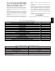
59SC2 FURNACE SIZE 040--- 10 060--- 10 060--- 14 080--- 16 080--- 20 100--- 14 100--- 20 120--- 20 A CABINET WIDTH B OUTLET WIDTH C BOTTOM INLET WIDTH D AIR INTAKE 14--- 3/16 (361) 12--- 1/2 (319) 12--- 9/16 (322) 7--- 1/8 (181) 17--- 1/2 (445) 15--- 7/8 (403) 16 (406) 8--- 3/4 (222) 21 (533) 19--- 3/8 (492) 19--- 1/2 (495) 10--- 1/2 (267) 24--- 1/2 (622) 22--- 7/8 (581) 23 (584) 12--- 1/4 (311) Fig. 1 -- Dimensional Drawing 6 SHIP WT. LB (KG) A12267 123.0 (55.4) 127.0 (57.2) 144.
THE BLOWER IS LOCATED BELOW THE BURNER SECTION, AND CONDITIONED AIR IS DISCHARGED UPWARD. THE BLOWER IS LOCATED TO THE LEFT OF THE BURNER SECTION, AND CONDITIONED AIR IS DISCHARGED TO THE RIGHT. THE BLOWER IS LOCATED ABOVE THE BURNER SECTION, AND CONDITIONED AIR IS DISCHARGED DOWNWARD A12181 Fig. 2 -- Multipoise Orientations 80 / 27˚C 60 / 16˚C SUPPLY AIR A10490 Fig. 3 -- Freeze Protection and Return Air Temperature BACK POSITIONED DOWNWARD BACK POSITIONED UPWARD AIR RETURN CUT IN BACK 18-IN.
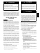
LOCATION 59SC2A ! ! CAUTION WARNING CARBON MONOXIDE POISONING / COMPONENT DAMAGE HAZARD PERSONAL INJURY AND/OR PROPERTY DAMAGE HAZARD Failure to follow this warning could result in personal injury or death and unit component damage. Improper use or installation of this furnace may result in premature furnace component failure.
WARNING ! CAUTION FIRE HAZARD FURNACE CORROSION HAZARD Failure to follow this warning could result in personal injury, death and/or property damage. Failure to follow this caution may result in furnace damage. Air for combustion must not be contaminated by halogen compounds, which include fluoride, chloride, bromide, and iodide. These elements can corrode heat exchangers and shorten furnace life.
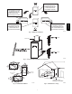
The opening shall commence within 12 in. (300 mm) of the ceiling. Appliances in the space shall have clearances of at least 1 in. (25 mm) from the sides and back and 6 in. (150 mm) from the front. The opening shall directly communicate with the outdoors or shall communicate through a vertical or horizontal duct to the outdoors or spaces (crawl or attic) that freely communicate with the outdoors.
Table 3 – Minimum Free Area Required for Each Combustion Air Opening or Duct to Outdoors TWO HORIZONTAL DUCTS (1 SQ. IN./2,000 BTUH) (1,100 SQ. MM/KW) FURNACE INPUT (BTUH) Free Area of Opening and Duct Sq. In (Sq. mm) 20 (12904) 30 (19355) 40 (25807) 50 (32258) 60 (38709) 70 (45161) 40,000* 60,000 80,000 100,000 120,000 140,000* Round Duct In. (mm) Dia 5 (127) 6 (152) 7 (178) 8 (203) 9 (229) 10 (254) SINGLE DUCT OR OPENING (1 SQ. IN./3,000 BTUH) (734 SQ. MM/KW) Free Area of Opening and Duct Sq. In (Sq.
59SC2A * Minimum opening size is 100 sq in. (64516 sq. mm) with minimum dimensions of 3‐in. (76mm) *Minimum dimensions of 3‐in. (76mm) NOTE: Use any of the following combinations of openings: A & B, C & D, D & E, F & G { Minimum of 3‐in. (76mm) when type‐B1 vent is used. L12F012 L12F013 Fig. 6 -- Air for Combustion, Ventilation, and Dilution for Outdoors Fig.
CONDENSATE TRAP NOTICE Condensate Trap -- Upflow Orientation When the furnace is installed in the upflow position, it is not necessary to relocate the condensate trap or associated tubing. Refer to Fig. 8 for upflow condensate trap information. Refer to Condensate Drain section for information how to install the condensate drain. The field--supplied, accessory horizontal drain trap grommet is ONLY REQUIRED FOR DIRECT VENT APPLICATIONS.
Remove pressure switch tube from front pressure switch and discard. A new tube is shipped in the loose parts bag. Remove relief tube from relief port on condensate trap. Remove tube from relief port. 59SC2A Remove the screw that secures the trap to the collector box and remove trap. Loosen clamp on inlet to vent elbow. Remove middle and bottom plugs. DO NOT DISCARD.
Remove plug from collector box. DO NOT DISCARD. 59SC2A If alternate vent position is required, loosen clamp on inlet of vent elbow. Remove the screw that secures the trap to the collector box and remove trap. Unconverted Factory Configuration As Viewed in the Horizontal Right Orientation NOTE: Remove knockout in casing before reïinstalling the condensate trap. Slide relief tube in standïoffs to adjust length. Vent elbow shown in alternate orientation. Tighten clamp on inlet to vent elbow 15 lb.ïin.
5 Remove the screw that secures the condensate trap to the collector box and remove trap. If alternate vent position is required, loosen clamp on vent elbow inlet. Remove relief tube from relief port on condensate trap. 59SC2A Remove front pressure switch tube and discard. A new tube is shipped in the Loose Parts bag. Remove relief tube from port on collector box. Remove middle and right plug from collector box. DO NOT DISCARD.
! CAUTION FROZEN AND BURST WATER PIPE HAZARD Failure to protect against the risk of freezing may result in property damage. Special precautions MUST be made if installing furnace in an area which may drop below freezing. This can cause improper operation or damage to equipment. If furnace environment has the potential of freezing, the drain trap and drain line must be protected. The use of accessory drain trap heaters, electric heat tape and/or RV antifreeze is recommended for these installations.
59SC2A the other side of the casing should be facing the front of the furnace. 11. Slide a spring clamp over the end of the remaining rubber drain elbow. 12. Attach the drain elbow to the angled end of Z-pipe and the drain trap outlet stub. Adjust the length of Z-pipe inserted into the grommet at the opposite side of the furnace as necessary for proper fit and positioning. In both upflow and downflow orientations, the Z-pipe should NOT be resting on any sheet metal parts. 13.
INSTALL CLAMPS ON DRAIN TUBE ATTACH DRAIN TUBE TO CONDENSATE DRAIN TRAP PULL DRAIN STUB THROUGH CASING Remove knockout. Install grommet before relocating condensate trap. OPEN SPRING CLAMP INSERT FACTORYïSUPPLIED 1/2ïIN. CPVC TO 3/4ïIN. PVC ADAPTER OR 1/2ïIN. CPVC PIPE *CLAMP MAY BE LOCATED ON OUTSIDE OF DRAIN TUBE A11342A A11582 Fig. 14 -- Formed Rubber Drain Grommet Fig.
INSTALLATION NOTICE This furnace is certified to leak 2% or less of nominal air conditioning CFM delivered when pressurized to 1--in. water column with all present air inlets, including bottom closure in upflow and horizontal applications, air outlets, and plumbing and electrical ports sealed. Upflow Installation NOTE: The furnace must be pitched as shown in Fig. 24 for proper condensate drainage.
WARNING ! Suspended Furnace Support The furnace must be supported under the entire length of the furnace with threaded rod and angle iron. See Fig. 29. Secure angle iron to bottom of furnace as shown. FIRE HAZARD Roll-- Out Protection A failure to follow this warning could cause personal injury, death and/or property damage. Provide a minimum 12--in. x 22--in. (305 x 559 mm) piece of sheet metal for flame roll--out protection in front of burner area for furnaces closer than 12--in.
59SC2A There are no provisions for an internal filter rack in these furnaces. An external filter is required and is purchased separately. A field supplied accessory air cleaner may also be used in place of the filter rack. For upflow applications, the filter can be installed on either side of the furnace, the bottom of the furnace or any combination of side and bottom of the furnace. See Fig. 18, 19, and 25.
14 x 25 Filter (356 x 635 mm) CFM L/s 600 (283) 800 (378) 1000 (472) 1200 (566) Factory-Accessory Washable (1-in. / 2.5 cm) 0.04 (12) 0.06 (15) 0.07 (18) 0.08 (20) Factory-Accessory Media* (4-in. / 10 cm) 0.05 (12) 0.07 (19) 0.10 (27) 0.14 (36) Representative After-Market Filter Media* Fiberglass* Pleated* (1-in. / 2.5 cm) (2-in. / 5 cm) (1-in. / 2.5 cm) (2-in. / 5 cm) 0.07 (17) 0.10 (26) 0.24 (60) 0.16 (40) 0.10 (25) 0.15 (39) 0.34 (85) 0.23 (59) 0.13 (34) 0.21 (52) 0.32 (81) 0.17 (43) 0.
Table 7 – Air Filter Selection and Duct Sizing -- In.
FURNACE (OR COIL CASING WHEN USED) FURNACE APPROVED COIL ASSEMBLY OR COIL BOX COMBUSTIBLE FLOORING COMBUSTIBLE FLOORING A PLENUM OPENING D DOWNFLOW SUBBASE FLOOR OPENING SHEET METAL PLENUM SHEET METAL PLENUM FLOOR OPENING C FLOOR OPENING A10491 Fig. 20 -- Installation on Combustible Flooring Table 8 – Opening Dimensions -- In. (mm) FURNACE CASING WIDTH IN.
UPFLOW PERFORATED DISCHARGE DUCT FLANGE DOWNFLOW HORIZONTAL 90° 90° YES YES YES 59SC2A 120° MIN YES 120° MIN YES YES 120° MIN NO NO NO A10493 Fig. 21 -- Duct Flanges 5/ 16″ (8mm) (8mm) 5/ 16″ 1 3/4″ (44mm) 1 3/4″ (44mm) (8mm) 5/16″ BOTTOM CLOSURE PANEL (8mm) 5/ 16″ (44mm) 1 3/ 4″ 3/ (44mm) 1 4″ BOTTOM PLATE A89014 A11092 Fig. 22 -- Leveling Legs Fig. 23 -- Removing Bottom Closure Panel LEVEL 0-IN. (0 MM) TO 1/2-IN. (13 MM) MAX MIN 1/4-IN. (6 MM) TO 1/2-IN.
A11036 A11037 Fig. 25 -- Upflow Return Air Configurations and Restrictions Fig. 26 -- Downflow Return Air Configurations and Restrictions HORIZONTAL TOP RETURN NOT PERMITTED FOR ANY MODEL A11038 Fig. 27 -- Horizontal Return Air Configurations and Restrictions 27 59SC2A ANY COMBINATION OF 1, 2, OR 3 PERMITTED.
COMBUSTION - AIR PIPE (SEE VENTING SECTION) 30 IN. (762 mm) MIN. WORK AREA 59SC2A 2-IN. (51 mm) ROLLOUT PROTECTION REQUIRED Install 12” x 22” (305 x 559 mm) sheet metal in front of burner compartment area. A11154 Fig. 28 -- Working Platform for Attic Installation NOTE: Local codes may require a drain pan and condensate trap when a condensing furnace is installed over a finished ceiling. COMBUSTION-AIR PIPE (SEE VENTING SECTION) 2-IN. (51 mm) A11155 Fig.
AIR DUCTS NOTICE Many states, provinces and localities are considering or have implemented standards and/or restrictions on duct sizing practices, ductwork leakage, and/or ductwork thermal, airflow and electrical efficiencies. CONSULT LOCAL CODE OFFICIALS for ductwork design and performance requirements in your area.
Table 9 – Air Delivery -- CFM (With Filter) UNIT SIZE 040---10 060---10 SIDE/BOTTOM SIDE/BOTTOM SIDE/BOTTOM 59SC2A 060---14 RETURN-AIR CONNECTION 080---16 080---20 100---14 100---20 120---20 140---20 SIDE/BOTTOM BOTTOM or TWO-SIDES 3,4 SIDE/BOTTOM BOTTOM or TWO-SIDES 3,4 BOTTOM or TWO-SIDES 3,4 BOTTOM or TWO-SIDES 3,4 EXTERNAL STATIC PRESSURE (IN.W.C.) SPEED TAPS 2 0.1 0.2 0.3 0.4 0.5 0.6 0.7 0.8 0.9 1.
GAS PIPING WARNING FIRE OR EXPLOSION HAZARD A failure to follow this warning could result in personal injury, death, and/or property damage. FIRE OR EXPLOSION HAZARD Failure to follow this warning could result in personal injury, death, and/or property damage. If local codes allow the use of a flexible gas appliance connector, always use a new listed connector. Do not use a connector which has previously served another gas appliance.
Table 10 – Maximum Capacity of Pipe NOMINAL IRON PIPE SIZE IN. (MM) 1/2 (13) 3/4 (19) 1 ( 25) 1-1/4 (32) 1-1/2 (39) Field--supplied wiring shall conform with the limitations of 63_F (33_C) rise. LENGTH OF PIPE --- FT (M) 10 (3.0) 20 (6.0) 30 (9.1) 40 (12.1) 50 (15.2) 175 360 680 1400 2100 120 250 465 950 1460 97 200 375 770 1180 82 170 320 660 990 73 151 285 580 900 ! ELECTRICAL SHOCK AND FIRE HAZARD Failure to follow this warning could result in personal injury, death, or property damage.
J--Box Installation WARNING FIRE OR ELECTRICAL SHOCK HAZARD Failure to follow this warning could result in personal injury, death, or property damage. If field--supplied manual disconnect switch is to be mounted on furnace casing side, select a location where a drill or fastener cannot damage electrical or gas components. The J-Box is used when field line voltage electrical connections are made to the furnace wiring harness inside the furnace casing.
alternate power supply must generate the same voltage, phase, and frequency (Hz) as shown in Table 11 or the furnace rating plate. Power from an alternate power supply that is non-sinusoidal may damage the furnace electronics or cause erratic operation. Contact the alternate power supply manufacturer for specifications and details.
To HUM Terminal On To Humidifier Leads Furnace Control Board 24 V Coil To Humidifier Leads To Com/24V Screw Terminal on Thermostat Strip A11157 Fig.
TWINNING AND/OR COMPONENT TEST TERMINAL BLOWER OFF-DELAY J2 JUMPER BLOWER OFF-DELAY 120 180 90 150 J2 HUMIDIFIER TERMINAL (24-VAC 0.5 AMP MAX.) G Com 24V 24-V THERMOSTAT TERMINALS W HUM R 0.
VENTING Special Venting Requirements for Installations in Canada Consignes spéciales pour l’installation de ventilation au Canada Installation in Canada must conform to the requirements of CSA B149 code. Vent systems must be composed of pipe, fittings, cements, and primers listed to ULC S636.
! WARNING CARBON MONOXIDE POISONING HAZARD 59SC2A Failure to follow the steps outlined below for each appliance connected to the venting system being placed into operation could result in carbon monoxide poisoning or death. The following steps shall be followed for each appliance connected to the venting system being placed into operation, while all other appliances connected to the venting system are not in operation: 1. Seal any unused openings in venting system. 2.
Table 12 – Vent Termination Kit for Direct Vent (2--pipe) Systems TERMINATION SYSTEM 2 ---in. (51 mm) Concentric Vent Kit 3 ---in. (76 mm) Concentric Vent Kit Single Penetration of Wall or Roof Single Penetration of wall or Roof NOTICE DIAMETER OF COMBUSTION AIR AND VENT PIPES --IN.
NOTICE RECOMMENDED SUPPORT FOR VENT TERMINATIONS 59SC2A It is recommended that sidewall vent terminations in excess of 24 inches (0.6 M) or rooftop terminations in excess of 36 inches (1 M) in vertical length be supported by EITHER the Direct Vent Termination Kit shown in Table 12 or by field--supplied brackets or supports fastened to the structure. When determining appropriate location for termination, consider the following guidelines: 1. Comply with all clearance requirements stated in Fig. 45 or Fig.
As an option to prevent moisture from trickling into the furnace vestibule, a trap can be installed in the intake air pipe near the furnace. Connecting a drain line to the trap is optional as trace amounts of moisture will evaporate into the intake air stream. If the combustion air inlet is located near a moisture exhaust duct, or there are other concerns of excessive moisture being drawn into the combustion air inlet, it is encouraged to connect a drain line to the trap.
NOTE: Pipe length (ft. / M) specified for maximum pipe lengths located in unconditioned spaces cannot exceed total allowable pipe length as calculated from Table 15 or 17. ! CARBON MONOXIDE POISONING HAZARD Configure the Furnace ! Failure to follow this warning could result in personal injury or death. WARNING DO NOT use cement to join polypropylene venting systems. Follow the polypropylene venting system manufacturer’s instructions for installing polypropylene venting systems.
! WARNING CARBON MONOXIDE POISONING HAZARD Failure to follow this warning could result in personal injury or death. DO NOT use cement to join polypropylene venting systems. Follow the polypropylene venting system manufacturer’s instructions for installing polypropylene venting systems. Optional Installation of the Vent Pipe NOTE: DO NOT USE THIS TECHNIQUE FOR POLYPROPYLENE VENTING SYSTEMS. This option provides a disconnect point for the vent pipe.
4. Disassemble loose pipe fittings. Clean and cement using same procedures as used for system piping. DO NOT CEMENT POLYPROPYLENE FITTINGS. NOTICE RECOMMENDED SUPPORT FOR VENT TERMINATIONS 59SC2A It is recommended that rooftop vent terminations in excess of 36 inches (1 M) in vertical length be supported by EITHER the Direct Vent Termination Kit shown in Table 12 or by field--supplied brackets or supports fastened to the structure.
Table 13 – Approved Combustion-Air and Vent Pipe, Fitting and Cement Materials (U.S.A.
Table 14 – Maximum Allowable Exposed Vent Lengths Insulation Table -- Ft. / M Maximum Length of Uninsulated and Insulated Vent Pipe-Ft (M) Single Stage Furnace Input Winter Design Temp ° F (° C) 20 (-10) 0 (-20) 40000 -20 (-30) 59SC2A -40 (-40) 20 (-10) 0 (-20) 60000 -20 (-30) -40 (-40) 20 (-10) 0 (-20) 80000 -20 (-30) -40 (-40) 20 (-10) 0 (-20) 100000 -20 (-30) -40 (-40) 20 (-10) 0 (-20) 120000 -20 (-30) -40 (-40) 20 (-10) 0 (-20) 140000 -20 (-30) -40 (-40) Pipe Length in Ft.
Table 15 – Maximum Equivalent Vent Length -- Ft. (M) 0 to 4500 Ft. (0 to 1370 M) Altitude NOTE: Maximum Equivalent Vent Length (MEVL) includes standard and concentric vent termination and does NOT include elbows. Use Table 16 - Deductions from Maximum Equivalent Vent Length to determine allowable vent length for each application.
Venting System Length Calculations The Total Equivalent Vent Length (TEVL) for EACH combustion air or vent pipe equals the length of the venting system, plus the equivalent length of elbows used in the venting system from Table 16. Standard vent terminations or factory accessory concentric vent terminations count for zero deduction. See vent system manufacturer’s data for equivalent lengths of flexible vent pipe or other termination systems.
Table 17 – Maximum Equivalent Vent Length -- Ft. (M) 4501 to 10,000 Ft. (0 to 1370 M) Altitude NOTE: Maximum Equivalent Vent Length (MEVL) includes standard and concentric vent termination and does NOT include elbows. Use Table 16 - Deductions from Maximum Equivalent Vent Length to determine allowable vent length for each application.
59SC2A Attach gaskets to vent pipe and combustion air adapters. Vent Coupling and Adapter A11314 Fig. 37 -- Vent Coupling and Adapter with Gaskets INDUCER OUTLET VENT ELBOW CLAMP TORQUE 15 LB-IN. VENT PIPE CLAMP TORQUE 15 LB-IN. PSC INDUCER ASSEMBLY VENT ELBOW INDUCER OUTLET CHOKE 40,000 BTUH MODELS ONLY A11285 Fig.
7 6 Any other unused knockout may be used for combustion air connection. 4 5 1 Rotate vent elbow to required position. 7 6 Any other unused knockout may be used for combustion air connection. 1 2 5 3 3 A11309 6 4 5 A11308 3 7 2 5 1 Any other unused knockout may be used for combustion air connection. 4 5 A11310 1 Attach vent pipe adapter with gasket to furnace casing. 2 Align notches in rubber coupling over standoffs on adapter. Slide clamps over the coupling.
3 Rotate vent elbow to required position. 2 5 4 1 Rotate vent elbow to required position. 5 4 5 1 2 5 3 Any other unused knockout may be used for combustion air connection. 6 7 6 A11311 7 59SC2A A11312 A11313 Downflow Vertical Requires Accessory Internal Vent Kit. See Product Data for current kit number. 1 Attach vent pipe adapter with gasket to furnace casing. 2 Align notches in rubber coupling over standoffs on adapter. Slide clamps over the coupling.
HORIZONTAL LEFT LEFT VENT CONFIGURATION HORIZONTAL LEFT RIGHT VENT CONFIGURATION* *Requires Accessory Internal Vent Kit See Product Data for Current Kit Number 1 Attach vent pipe adapter with gasket to furnace casing. 2 Align notches in rubber coupling over standoffs on adapter. Slide clamps over the coupling. 3 Slide vent pipe through adapter and coupling into vent elbow. 4 Insert vent pipe into vent elbow. 5 Torque all clamps 15 lb.-in. 6 Attach combustion air pipe adapter with gasket to furnace.
59SC2A HORIZONTAL RIGHT VERTICAL VENT CONFIGURATION HORIZONTAL RIGHT LEFT VENT CONFIGURATION* *Requires Internal Vent Kit See Product Data for Current Kit Number HORIZONTAL RIGHT RIGHT VENT CONFIGURATION 1 Attach vent pipe adapter with gasket to furnace casing. 2 Align notches in rubber coupling over standoffs on adapter. Slide clamps over the coupling. 3 Slide vent pipe through adapter and coupling into vent elbow. 4 Insert vent pipe into vent elbow. 5 Torque all clamps 15 lb.-in.
ALIGN NOTCHES IN VENT PIPE COUPLING OVER STAND-OFF ON ADAPTER. TORQUE LOWER CLAMP 15 LB-IN. WHEN REMAINING VENT PIPE IS INSTALLED, TORQUE UPPER CLAMP TO 15 LB-IN. 59SC2A VENT PIPE ADAPTER WITH GASKET INSTALLED ON FURNACE VENT PIPE IS CUT FLUSH WITH TOP OF ADAPTER. VENT PIPE FLUSH WITH ADAPTER VENT PIPE FLUSH SHOWING COUPLING A11339 Fig.
V 59SC2A V A12326 NOTE: The following is based upon National codes for gas appliances and is provided as a reference. Refer to local codes which may supersede these standards and/or recommendations.
V 59SC2A V A12325 NOTE: The following is based upon National codes for gas appliances and is provided as a reference. Refer to local codes which may supersede these standards and/or recommendations.
Roof Termination (Preferred) Vertical separation between combustion air and vent At least 36 in. (914mm) Note: “A” denotes 0 To 2 in. (51mm) Between the first 2 vents Third vent (and fourth vent, if used) must be 36 in. Away (914mm) A 8 ¾ in. (222mm) or 3 in.(76mm) 18 in. Maximum (457mm) 6 ¾ in. (172mm) or 2in. (51mm) Note: 36ïin. separation between pairs of inlets only required for directïvent systems A Maintain 12 in. (305mm) min. Clearance above highest anticipated snow level maximum of 24 in.
OPTIONAL TERMINATION BRACKET FOR 2-PIPE TERMINATIONS 59SC2A OPTIONAL BRACKET COUPLING 12-IN. (305 MM) 12 IN. (305 MM) SEPARATION BETWEEN BOTTOM OF COMBUSTION AIR AND BOTTOM OF VENT. MAINTAIN 12 IN. (305 MM) CLEARANCE ABOVE HIGHEST ANTICIPATED SNOW LEVEL OR GRADE, WHICHEVER IS GREATER. 12-IN. (305 MM) ABOVE ANTICIPATED SNOW LEVEL COMBUSTION-AIR (ELBOW PARALLEL TO WALL) OVERHANG EXHAUST CLEARANCE TO OVERHANG PER CODE 12 IN. (305 MM) MIN. GROUND LEVEL OR SNOW LEVEL A12221 Fig.
Ventilated Combustion Air intake pipe Pipe hangar 59SC2A 3” (76 mm) 12” (305 mm) Ventilated Combustion Air intake termination in crawl space CRAWL SPACE highest level of insulation ATTIC A10497 Fig.
A12220 Fig. 51 -- Sample Inlet Air Pipe Connection for Polypropylene Venting Systems TO CODEïAPPROVED DRAIN OR CONDENSATE PUMP Representative drawing only, some models may vary in appearance L1 L12F028 Fig. 52 -- Optional Combustion Air Inlet Moisture Trap 61 59SC2A EXAMPLE FOR UPFLOW INSTALLATIONS. MAY BE APPLIED TO OTHER CONFIGURATIONS.
START--UP, ADJUSTMENT, AND SAFETY CHECK 1. Remove upper and middle collector box drain plugs opposite of the condensate trap. See Fig. 59. 2. Connect field-supplied 5/8--in. (16 mm) ID tube with attached funnel to upper collector box drain connection. See Fig. 59). 3. Pour one quart (liter) of water into funnel/tube. Water should run through collector box, overfill condensate trap, and flow into open field drain. 4. Remove funnel; replace collector box drain plug. 5. Connect field-supplied 5/8-in.
The NATURAL GAS manifold pressure adjustments in Table 21 compensate for BOTH altitude AND gas heating value. DO NOT apply an additional de--rate factor to the pressures show in Table 21. The values in this table are NOT referenced to sea level; they are AS--MEASURED AT ALTITUDE. The heating content of natural gas at altitude may already provide for a reduction in capacity of the furnace.
WARNING ! (Read following caution before changing taps). ! FIRE HAZARD UNIT DAMAGE HAZARD Failure to follow this warning could result in personal injury, death, and/or property damage. To avoid operating outside the rise range and avoid component damage: Reinstall manifold pressure tap plug in gas valve to prevent gas leak. Refer to the Air Delivery Tables to determine which airflows and settings are allowed for proper heating airflow. DO NOT use the highlighted settings for Heating airflow.
Check Safety Controls PERCENT OF DERATE 0 4--- 6 6--- 8 8--- 10 10--- 12 12--- 14 14--- 16 16--- 18 18--- 20 ALTITUDE FT. M 0–2000 2001–3000 3001–4000 4001–5000 5001–6000 6001–7000 7001–8000 8001–9000 9001–10,000 0--- 610 610--- 914 914--- 1219 1219--- 1524 1524--- 1829 1829--- 2134 2134--- 2438 2438--- 2743 2743--- 3048 DERATE MULTIPLIER FACTOR* 1.00 0.95 0.93 0.91 0.89 0.87 0.85 0.83 0.81 *Derate multiplier factors are based on midpoint altitude for altitude range.
59SC2A 338309-201 Rev. E A11602 Fig.
SECONDS FOR 1 REVOLUTION 10 11 12 13 14 15 16 17 18 19 20 21 22 23 24 25 26 27 28 29 30 31 32 33 34 35 36 37 38 39 40 41 42 43 44 45 46 47 48 49 SECONDS FOR 1 REVOLUTION 50 51 52 53 54 55 56 57 58 59 60 62 64 66 68 70 72 74 76 78 80 82 84 86 88 90 92 94 96 98 100 102 104 106 108 110 112 116 120 67 SIZE OF TEST DIAL 1 Cu Ft. 2 Cu Ft. 5 Cu Ft.
Table 21 – Orifice Size and Manifold Pressure (in. w.c.) for Gas Input Rate SINGLE-STAGE FURNACE (TABULATED DATA BASED ON 20,000 BTUH PER BURNER, DERATED 2%/1000 FT (305M) ABOVE SEA LEVEL) ALTITUDE AVG. GAS RANGE HEAT VALUE U.S.A. and Canada U.S.A. Only U.S.A. Only 0.62 0.64 Orifice Manifold Orifice Manifold Orifice Manifold Orifice Manifold (Btu/cu ft) No. Pressure No. Pressure No. Pressure No. Pressure 900 43 3.8 42 3.2 42 3.3 42 3.4 925 43 3.6 43 3.7 43 3.8 42 3.
Table 21 -- Orifice Size and Manifold Pressure (in. w.c.) for Gas Input Rate (Cont.) SINGLE-STAGE FURNACE (TABULATED DATA BASED ON 20,000 BTUH PER BURNER, DERATED 2%/1000 FT (305M) ABOVE SEA LEVEL) AVG. GAS RANGE HEAT VALUE U.S.A. Only ft (m) U.S.A. Only 0.60 0.62 0.64 AT ALTITUDE Orifice Manifold Orifice Manifold Orifice Manifold Orifice Manifold (Btu/cu ft) No. Pressure No. Pressure No. Pressure No. Pressure 650 42 3.4 42 3.5 42 3.6 42 3.7 7001 675 43 3.8 42 3.
SERVICE AND MAINTENANCE PROCEDURES ! Electrical Controls and Wiring ! WARNING ELECTRICAL SHOCK HAZARD FIRE, INJURY OR DEATH HAZARD Failure to follow this warning could result in personal injury or death. Failure to follow this warning could result in personal injury, death and/or property damage. 59SC2A The ability to properly perform maintenance on this equipment requires certain knowledge, mechanical skills, tools, and equipment.
Component Self-Test ! Care and Maintenance ! FIRE OR EXPLOSION HAZARD Failure to follow this warning could result in personal injury, death and/or property damage. Never store flammable or combustible materials on, near, or in contact with the furnace, such as: 1. Spray or aerosol cans, rags, brooms, dust mops, vacuum cleaners, or other cleaning tools. 2.
2. Check blower motor and wheel for cleanliness each heating and cooling season. Clean as necessary. 3. Check electrical connections for tightness and controls for proper operation each heating season. Service as necessary. 4. Inspect burner compartment before each heating season for rust, corrosion, soot or excessive dust. If necessary, have furnace and burner serviced by a qualified service agency. 5.
! WARNING ELECTRICAL OPERATION HAZARD Failure to follow this warning could result in personal injury or death. Blower door switch opens 115--v power to control. No component operation can occur unless switch is closed. Caution must be taken when manually closing this switch for service purposes. 16. Downflow or horizontal furnaces with vent pipe through furnace only: a. Install and connect short piece of vent pipe inside furnace to existing vent. b. Connect vent connector to vent elbow. 17.
! WARNING FIRE OR EXPLOSION HAZARD Failure to follow this warning could result in personal injury, death, and/or property damage. 59SC2A Never purge a gas line into a combustion chamber. Never test for gas leaks with an open flame. Use a commercially available soap solution made specifically for the detection of leaks to check all connections. A fire or explosion may result causing property damage, personal injury or loss of life. 14.
Checking Heat Pad Operation (If Applicable) In applications where the ambient temperature around the furnace is 32_F or lower, freeze protection measures are required. If this application is where heat tape has been applied, check to ensure it will operate when low temperatures are present. NOTE: The Heat Pad, when used, should be wrapped around the condensate drain trap. There is no need to use heat tape within the furnace casing.
reach 32_F (0_C) or lower unless winterized. Follow these procedures to winterize your furnace: ! CAUTION 2 − in. 50 mm UNIT COMPONENT DAMAGE HAZARD Failure to follow this caution may result in damage to the furnace and other property damage. 3/8 − in. 9.6 mm 59SC2A Do not use ethylene glycol (automotive antifreeze coolant or equivalent). Failure of plastic components may occur. 3/16 − in. 4.6 mm 1. Obtain propylene glycol (RV/swimming pool antifreeze or equivalent). 2.
GROMMET MOTOR SHAFT FLAT MOTOR ARM SCREW SET SCREW MOTOR WHEEL HUB SEE DETAIL A 59SC2A SCREW LOCATION BLOWER HSG ASSY BRACKET BRACKET ENGAGEMENT DETAIL A CUTOFF, BLOWER WHEEL, BLOWER BLOWER HSG ASSY BRACKET CAPACITOR OR POWER CHOKE (WHEN USED) MOTOR, BLOWER SCREW (GND) A11584 Fig.
IGNITER BURNER SUPT. ASSY BRACKET, IGNITER BURNER ASSY 59SC2A FLAME ROLLOUT SWITCH FLAME SENSOR (BELOW BURNER) A11403 Fig.
NOTE: Furnace control must be grounded for proper operation or control will lock out. Control is grounded through green/yellow wire routed to gas valve and manifold bracket screw. Using the schematic diagram in Fig. 65, follow the sequence of operation through the different modes. Read and follow the wiring diagram very carefully.
Fig. 64 -- Troubleshooting Guide A11622 80 YES Go to section below for the status code that was flashed. Determine status code.
Troubleshooting Guide (Cont) A11440 81 24 SECONDARY VOLTAGE FUSE IS OPEN Check for: - Short circuit in secondary voltage (24V) wiring including thermostat leads. Disconnect thermostat leads to isolate short circuit. 23 PRESSURE SWITCH DID NOT OPEN – Check for: - Obstructed pressure tube. - Pressure switch stuck closed. 22 ABNORMAL FLAME-PROVING SIGNAL Flame is proved while gas valve is deenergized. Inducer will run until fault is cleared. Check for: - Stuck open or leaky gas valve.
59SC2A 338309-201 Rev. E A11603 Fig.
PARTS REPLACEMENT INFORMATION GUIDE Casing Group Gas Control Group Blower door Bottom plate Control door Door knob assembly Top filler plate Burner Flame sensor Gas valve Hot surface igniter Manifold Orifice 3--Amp fuse Circuit board Control box Door switch Junction box Limit switch(es) Transformer Heat Exchanger Group Blower Group Inducer Group Blower housing Blower motor Blower wheel Capacitor (when used) Capacitor strap (when used) Cut--off plate Power choke (where used) Collector box Condensate
59SC2A Copyright 2012 Carrier Corp. S 7310 W. Morris St. S Indianapolis, IN 46231 . Edition Date: 06/12 Manufacturer reserves the right to change, at any time, specifications and designs without notice and without obligations.