
Instruction manual


6
6 15/16
[176.1]
3
[76.2]
3
[76.2]
6 11/16
[170.1]
23 5/16
[592.9]
25 1/8
[638.7]
26 3/8
[670.0]
26 11/16
[678.1]
21
[534.0]
26 5/16
[668.8]
17 5/16
[439.2]
16 9/16
[420.9]
20 1/4
[513.9]
25 3/16
[639.1]
28 3/16
[715.9]
28 5/8
[726.4]
32 5/8
[829.5]
28 3/4
[730.5]
26 3/8
[669.9]
26 11/16
[678.1]
21 15/16
[557.4]
21 1/16
[535.8]
26 5/16
[668.8]
3
[76.2]
AIR INTAKE
1 3/4
[44.5]
GAS CONN
7/8
[22.2]
7/8
[22.2] POWER CONN
7/8
[22.2]
THERMOSTAT ENTRY
7/8
[22.2]
3
[76.2]
AIR INTAKE
1 3/4
[44.5]
GAS CONN
7/8
[22.2]
7/8
[22.2]
3
[76.2 ]
7/8
[22.2]
7/8
[22.2]
THERMOSTAT ENTRY
22 15/16
[581.9]
16 9/16
[420.9]
17 7/16
[442.3]
20 1/4
[513.9]
24
[609.7]
28 3/8
[720.4]
28 5/8
[726.9]
29 13/16
[757]
23 3/8
[592.0]
3
[76.2]
VENT
1 (BOTH SIDES)
[25.4]
D
2 3/10
[58.4]
C
BOTTOM RETURN
WIDTH
11/16
[17.5]
11/16
[17.5]
B
OUTLET WIDTH
A
22
[558.3] (BOTH SIDES)
14 13/16
[376.3]
35
[889.0]
5/8
[15.8]
1 5/16
[33.3]
29 1/2
[749.3]
19 1/8
[485.8]
20 5/8
[522.7]
23 7/16
[595.6]
[101.6]
4
[63.5]
2 1/2
18 1/16
[458.6]
2 1/2
[63.5]
4
[101.6]
20 5/8
[522.7]
BOTTOM INLET
21 5/8
[549.5]
6 1/16
[154.0]
PART NUMBER
SD5024-4
SHT
1
REV
E
NEXT SHEET
2
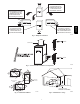
VENT
AIR INTAKE
AIR FLOW
AIR FLOW
SIDE INLET
SIDE INLET
CONDENSATE DRAIN TRAP
LOCATION
NOTE: ALL DIMENSIONS IN INCH [MM]
[22.2]
7/8
7/8
[22.2] POWER CONN
AIR FLOW
SEE NOTE #3
NOTES:
1. Doors may vary by model.
2. Minimum return-air openings at furnace, based on metal duct. If ex duct is used,
see ex duct manufacturer's recommendations for equivalent diameters.
a. For 800 CFM-16-in. (406 mm) round or 14 1/2 x 12-in. (368 x 305 mm) rectangle.
b. For 1200 CFM-20-in. (508 mm) round or 14 1/2 x 19 1/2-in. (368 x 495 mm) rectangle.
c. For 1600 CFM-22-in. (559 mm) round or 14 1/2 x 22 1/16-in. (368 x 560mm) rectangle.
d. Return air above 1800 CFM at 0.5 in. w.c. ESP on 24.5" casing, requires one of the following
congurations: 2 sides, 1 side and a bottom or bottom only. See Air Delivery table in this
document for specic use to allow for sucient airow to the furnace.
3. Vent and Combustion air pipes through blower compartment must
use accessory “Vent Kit - Through the Cabinet”. See accessory list for
current part number.
TOP VIEW
A12267
59SC2
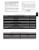
FURNACE SIZE
A B C D
SHIP WT.
LB (KG)
CABINET WIDTH OUTLET WIDTH BOTTOM INLET WIDTH AIR INTAKE
040---10
14---3/16 (361) 12---1/2 (319) 12---9/16 (322) 7---1/8 (181)
123.0 (55.4)
060---10 127.0 (57.2)
060---14
17---1/2 (445) 15---7/8 (403) 16 (406) 8---3/4 (222)
144.0 (64.8)
080---16 154.0 (69.3)
080---20
21 (533) 19---3/8 (492) 19---1/2 (495) 10---1/2 (267)
161.5 (72.7)
100---14 168.5 (75.8)
100---20 168.5 (75.8)
120---20 24---1/2 (622) 22---7/8 (581) 23 (584) 12---1/4 (311) 186.0 (83.7)
Fig. 1 -- Dimensional Drawing
59SC2A