
Service manual
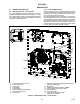

Table Of Contents
- SAFETY SUMMARY
- INTRODUCTION
- DESCRIPTION
- MICROPROCESSOR
- 3.1 TEMPERATURE CONTROL MICROPROCESSOR SYSTEM
- 3.2 CONTROLLER SOFTWARE
- 3.3 MODES OF OPERATION
- 3.4 PROTECTION MODES OF OPERATION
- 3.5 QUEST - CCPC
- 3.6 CONTROLLER ALARMS
- 3.7 PRE-TRIP DIAGNOSTICS
- 3.8 DataCORDER
- 3.9 CONTROLLER CONFIGURATION VARIABLES
- 3.10 CONTROLLER FUNCTION CODES
- 3.11 CONTROLLER ALARM INDICATIONS
- 3.12 CONTROLLER PRE-TRIP TEST CODES
- OPERATION
- TROUBLESHOOTING
- 5.1 UNIT WILL NOT START OR STARTS THEN STOPS
- 5.2 UNIT OPERATES LONG OR CONTINUOUSLY IN COOLING
- 5.3 UNIT RUNS BUT HAS INSUFFICIENT COOLING
- 5.4 UNIT WILL NOT HEAT OR HAS INSUFFICIENT HEATING
- 5.5 UNIT WILL NOT TERMINATE HEATING
- 5.6 UNIT WILL NOT DEFROST PROPERLY
- 5.7 ABNORMAL PRESSURES
- 5.8 ABNORMAL NOISE OR VIBRATIONS
- 5.9 MICROPROCESSOR MALFUNCTION
- 5.10 NO EVAPORATOR AIR FLOW OR RESTRICTED AIR FLOW
- 5.11 EAUTOFRESH NOT OPERATING
- 5.12 ELECTRONIC EXPANSION VALVE MALFUNCTION
- 5.13 AUTOTRANSFORMER MALFUNCTION
- 5.14 COMPRESSOR OPERATING IN REVERSE
- 5.15 ABNORMAL TEMPERATURES
- 5.16 ABNORMAL CURRENTS
- SERVICE
- 6.1 SECTION LAYOUT
- 6.2 MANIFOLD GAUGE SET
- 6.3 SERVICE CONNECTIONS
- 6.4 PUMP DOWN THE UNIT
- 6.5 REFRIGERANT LEAK CHECKING
- 6.6 EVACUATION AND DEHYDRATION
- 6.7 REFRIGERANT CHARGE
- 6.8 COMPRESSOR
- 6.9 HIGH PRESSURE SWITCH
- 6.10 CONDENSER COIL
- 6.11 CONDENSER FAN AND FAN MOTOR
- 6.12 FILTER DRIER
- 6.13 EVAPORATOR COIL & HEATER ASSEMBLY
- 6.14 EVAPORATOR FAN AND MOTOR ASSEMBLY
- 6.15 EVAPORATOR SECTION CLEANING
- 6.17 ECONOMIZER SOLENOID VALVE
- 6.18 ECONOMIZER EXPANSION VALVE
- 6.19 DIGITAL UNLOADER VALVE
- 6.20 VALVE OVERRIDE CONTROLS
- 6.21 AUTOTRANSFORMER
- 6.22 CONTROLLER
- 6.23 TEMPERATURE SENSOR SERVICE
- 6.24 VENT POSITION SENSOR (VPS)
- 6.25 eAutoFresh SERVICE
- 6.26 MAINTENANCE OF PAINTED SURFACES
- 6.27 COMMUNICATIONS INTERFACE MODULE INSTALLATION
- ELECTRICAL WIRING SCHEMATICS
1−1T−362
SECTION 1
INTRODUCTION
1.1 INTRODUCTION
The Carrier Transicold model 69NT40−561−200 − 299
series units are of lightweight aluminum frame
construction, designed to fit in the front of a container
and serve as the container’s front wall.
They are one piece, self−contained, all electric units,
which include cooling and heating systems to provide
precise temperature control.
The units are supplied with a complete charge of
refrigerant R−134a and compressor lubricating oil, and
are ready for operation upon installation. Forklift
pockets are provided for unit installation and removal.
The base unit operates on nominal 380/460 volt,
3−phase, 50/60 hertz (Hz) power. An optional
autotransformer may be fitted to allow operation on
nominal 190/230, 3−phase, 50/60 Hz power. Control
system power is provided by a transformer which steps
the supply power down to 18 and 24 volts, single phase.
The controller is a Carrier Transicold Micro−Link 3
microprocessor. The controller operates automatically
to select cooling, holding or heating as required to
maintain the desired set point temperature within very
close limits. The unit may also be equipped with an
electronic temperature recorder.
The controller has a keypad and display for viewing or
changing operating parameters. The display is also
equipped with lights to indicate various modes of
operation.
1.2 CONFIGURATION IDENTIFICATION
Unit identification information is provided on a plate
located on the back wall of the condenser section. The
plate provides the unit model number, the unit serial
number and the unit parts identification number (PID).
The model number identifies the overall unit
configuration, while the PID number provides
information on specific optional equipment, factory
provisioned to allow for field installation of optional
equipment and differences in detailed parts.
1.3 FEATURE DESCRIPTIONS
1.3.1 Control Box
Units are equipped with an aluminum control box, and
may be fitted with a lockable door.
1.3.2 Temperature Readout
The unit is fitted with suction and discharge refrigerant
temperature sensors. The sensor readings may be
viewed on the controller display.
1.3.3 Pressure Readout
The unit is fitted with evaporator, suction, and discharge
pressure transducers. The transducer readings may be
viewed on the controller display.
1.3.4 Compressor
The unit is fitted with a scroll compressor equipped with
suction and discharge service connections.
1.3.5 Condenser Coil
The unit is fitted with a two−row square formed
condenser coil using 7mm tubing.
1.3.6 Evaporator
The evaporator section is equipped with an electronic
expansion valve (EEV).
1.3.7 Evaporator Fan Operation
Units are equipped with three−phase evaporator fan
motors. Opening of an evaporator fan internal protector
will shut down the unit.
1.3.8 Plate Set
Each unit is equipped with a tethered set of wiring
schematics and wiring diagram plates. The plate sets
are ordered using a seven−digit base part number and a
two−digit dash number.
1.4 OPTION DESCRIPTIONS
Various options may be factory or field equipped to the
base unit. These options are described in the following
sub−paragraphs.
1.4.1 Battery
The refrigeration controller may be fitted with standard
replaceable batteries or a rechargeable battery pack.
Rechargeable battery packs may be fitted in the
standard location or in a secure location.
1.4.2 Dehumidification
The unit may be fitted with a humidity sensor. This
sensor allows setting of a humidity set point in the
controller. In dehumidification mode, the controller will
operate to reduce internal container moisture level.
1.4.3 USDA
The unit may be supplied with fittings for additional
temperature probes, which allow recording of USDA
Cold Treatment data by the integral DataCORDER
function of the Micro−Link refrigeration controller.
1.4.4 Interrogator
Units that use the DataCORDER function are fitted with
interrogator receptacles for connection of equipment to
download the recorded data. Two receptacles may be
fitted; one is accessible from the front of the container
and the other is mounted inside the container (with the
USDA receptacles).
1.4.5 Remote Monitoring
The unit may be fitted with a remote monitoring
receptacle. This item allows connection of remote
indicators for COOL, DEFROST and IN RANGE.
Unless otherwise indicated, the receptacle is mounted
at the control box location.