
Service manual
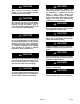
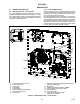

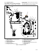
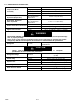
Table Of Contents
- SAFETY SUMMARY
- INTRODUCTION
- DESCRIPTION
- MICROPROCESSOR
- 3.1 TEMPERATURE CONTROL MICROPROCESSOR SYSTEM
- 3.2 CONTROLLER SOFTWARE
- 3.3 MODES OF OPERATION
- 3.4 PROTECTION MODES OF OPERATION
- 3.5 QUEST - CCPC
- 3.6 CONTROLLER ALARMS
- 3.7 PRE-TRIP DIAGNOSTICS
- 3.8 DataCORDER
- 3.9 CONTROLLER CONFIGURATION VARIABLES
- 3.10 CONTROLLER FUNCTION CODES
- 3.11 CONTROLLER ALARM INDICATIONS
- 3.12 CONTROLLER PRE-TRIP TEST CODES
- OPERATION
- TROUBLESHOOTING
- 5.1 UNIT WILL NOT START OR STARTS THEN STOPS
- 5.2 UNIT OPERATES LONG OR CONTINUOUSLY IN COOLING
- 5.3 UNIT RUNS BUT HAS INSUFFICIENT COOLING
- 5.4 UNIT WILL NOT HEAT OR HAS INSUFFICIENT HEATING
- 5.5 UNIT WILL NOT TERMINATE HEATING
- 5.6 UNIT WILL NOT DEFROST PROPERLY
- 5.7 ABNORMAL PRESSURES
- 5.8 ABNORMAL NOISE OR VIBRATIONS
- 5.9 MICROPROCESSOR MALFUNCTION
- 5.10 NO EVAPORATOR AIR FLOW OR RESTRICTED AIR FLOW
- 5.11 EAUTOFRESH NOT OPERATING
- 5.12 ELECTRONIC EXPANSION VALVE MALFUNCTION
- 5.13 AUTOTRANSFORMER MALFUNCTION
- 5.14 COMPRESSOR OPERATING IN REVERSE
- 5.15 ABNORMAL TEMPERATURES
- 5.16 ABNORMAL CURRENTS
- SERVICE
- 6.1 SECTION LAYOUT
- 6.2 MANIFOLD GAUGE SET
- 6.3 SERVICE CONNECTIONS
- 6.4 PUMP DOWN THE UNIT
- 6.5 REFRIGERANT LEAK CHECKING
- 6.6 EVACUATION AND DEHYDRATION
- 6.7 REFRIGERANT CHARGE
- 6.8 COMPRESSOR
- 6.9 HIGH PRESSURE SWITCH
- 6.10 CONDENSER COIL
- 6.11 CONDENSER FAN AND FAN MOTOR
- 6.12 FILTER DRIER
- 6.13 EVAPORATOR COIL & HEATER ASSEMBLY
- 6.14 EVAPORATOR FAN AND MOTOR ASSEMBLY
- 6.15 EVAPORATOR SECTION CLEANING
- 6.17 ECONOMIZER SOLENOID VALVE
- 6.18 ECONOMIZER EXPANSION VALVE
- 6.19 DIGITAL UNLOADER VALVE
- 6.20 VALVE OVERRIDE CONTROLS
- 6.21 AUTOTRANSFORMER
- 6.22 CONTROLLER
- 6.23 TEMPERATURE SENSOR SERVICE
- 6.24 VENT POSITION SENSOR (VPS)
- 6.25 eAutoFresh SERVICE
- 6.26 MAINTENANCE OF PAINTED SURFACES
- 6.27 COMMUNICATIONS INTERFACE MODULE INSTALLATION
- ELECTRICAL WIRING SCHEMATICS
2−2T-362
2.1.3 Evaporator Section
The evaporator section is shown below. The evaporator
fans circulate air through the container by pulling it in the
top of the unit, directing it through the evaporator coil
where it is heated or cooled, and discharging it at the
bottom.
If the unit is equipped with eAutoFresh, system compon-
ents are mounted in addition to the standard refrigera-
tion unit components. The stepper motor component is
installed in the vent; the air filter, CO
2
sensor, stepper
motor drive and CO
2
sensing lines are installed on the
rib of the upper grill.
Most evaporator components are accessible by remov-
ing the upper rear panel (as shown in the illustration) or
by removing the evaporator fan access panels (see
Figure 2−1).
1
2
3
4
5
6
7
8
9
10
11
12
13
1. Evaporator Fan Motor #1 (EM1)
2. Return Recorder Sensor/Temperature Sensor
(RRS/RTS)
3. Humidity Sensor (HS)
4. Evaporator Fan Motor #2 (EM2)
5. Evaporator Coil Heaters (Underside of Coil)
6. Evaporator Coil
7. Electronic Expansion Valve (EEV)
8. Evaporator Temperature Sensors (Location)
(ETS1 & ETS2)
9. Interrogator Connector (Rear) (ICR)
10. USDA Probe Receptacle PR2
11. USDA Probe Receptacle PR1
12. USDA Probe Receptacle PR3
13. Cargo Probe Receptacle PR4
Figure 2−2 Evaporator Section