
Instruction manual

on, it will remain on until the demand is satisfied. The following
cycle will start with the heat pump. Outdoor temperatures of 5, 10,
15, 20, 25, 30, 35, 40, 45, 50, or 55°F or OF (off) may be selected.
If OF (off) is selected, outdoor temperature does not affect system
operation. Factory default is OF (off).
AVAILABLE SELECTIONS:
Use UP and DOWN buttons to move between 5 and 55 or OF (off)
in steps of 5.
OPTION 12—DEFROST HEAT SELECTION
A new feature that allows heat pump defrost cycles to always run
to completion and includes a software selectable amount of aux
heat during defrost. The equipment controller now senses 24vac on
the O line (which it did not put there) during a defrost. In response
to this, it maintains the Y signal as long as the O signal exists,
assuring defrost runs to completion. It now can also turn on W1
and/or W2 during defrost to control the amount of defrost heat.
Option 12 makes this selection. Select O for no heat, 1 for W1 on,
2 for W1 and W2 on, and 3 for W2 only on. This last selection is
only available if 3-stage heat is selected by turning DIP switch 3
off. When 1, 2 or 3 are selected, no wire should be connected
between the W terminals of the heat pump and the indoor unit.
Factory default is 0.
AVAILABLE SELECTIONS:
Use UP and DOWN buttons to move between 0, 1, 2, or 3.
OPTION 13—ZONE TEMPERATURE OFFSET ADJUSTMENT
Each zone temperature reading can be independently offset by up
to plus or minus 5 degrees F. While Option 13 is selected, the
NEXT ZONE button moves between zones and the UP and
DOWN buttons select an offset value between -5 and +5 degrees
F in 1 degree F steps. The offset number is added to the actual zone
temperature to produce the offset zone temperature, which is
displayed and used by the system. Factory default value is 0.
AVAILABLE SELECTIONS:
Use UP and DOWN buttons to move between -5 and 5 in steps of
1.
OPTION 14—HEAT/COOL DEADBAND ADJUSTMENT
The minimum allowable difference between the heat and cool set
points can be selected to any value between 0 and 6 degrees F. The
factory default value is 2. Higher numbers provide less precise
temperature control but save energy. Lower numbers provide
comfort with more energy use. If the deadband is set to less than
2, the mode is set to auto changeover, and the auto changeover
timer is small (see Option #38), continuous alternating heat and
cool cycles may occur. This wastes energy, but may be desired to
reduce humidity. When used with the ’COOL TO DEHUMIDIFY’
selection, effective cooling with reheat can occur.
AVAILABLE SELECTIONS:
Use UP and DOWN buttons to move between 0 and 6 in steps of
1.
OPTION 15—ENABLE AUTO MODE
In some applications, auto changeover from heat to cool may not
be desired. Option 15 selects ON or OF (off) for auto changeover.
When OF, the AUTO mode icon never appears, disabling the
AUTO mode. Factory default is ON.
AVAILABLE SELECTIONS:
Use UP or DOWN buttons to alternate between OF (off) and ON.
OPTION 16—ENABLE SUPER COMFORT HEAT MODE
The Comfort Heat operation is the same as that for the Thermi-
distat. This selection is only available if heat pump (DIP switch 1)
and variable speed blower (Option 5) selections are already made.
While heat pump is heating, the blower speed is reduced (by
removal of the G signal) for outdoor temperatures between 12 and
40 degrees F., providing warmer leaving air temperatures. For heat
pumps with electric aux heat and outdoor temperatures below 12
degrees F., any heat call is accompanied by a W1 signal, bringing
on the first stage of aux heat to again increase leaving air
temperature. Factory default is OF (off).
AVAILABLE SELECTIONS:
Use UP or DOWN buttons to alternate between OF (off) and ON.
OPTION 18—HUMIDITY OFFSET ADJUSTMENT
Like the zone temperature offset, the humidity reading can be
offset by plus or minus 10% in 1% steps. This offset adjusts the
humidity sensor output and therefore affects both humidify and
dehumidify performance. Factory default is 0.
AVAILABLE SELECTIONS:
Use UP and DOWN buttons to move between -10 and 10 in steps
of 1.
OPTION 19—OUTDOOR TEMPERATURE OFFSET ADJUST-
MENT
Use this option to offset the outdoor temperature reading within a
range of plus or minus 5 degrees F. Factory default is 0.
AVAILABLE SELECTIONS:
Use up and down buttons to move between -5 and 5 in steps of 1.
OPTION 20—ENABLE PROGRAMMABLE FAN
This option allows the blower to operate continuously (fan = ON)
during the day and automatically (fan = AUTO) at night. When
enabled, if the fan mode is set to ON, it will operate in AUTO
during the Zone 1 SLEEP period. Factory default is OF (off).
OTHER AVAILABLE SELECTIONS:
Still using UP or DOWN buttons to alternate between OF (off) and
ON.
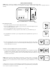
Options 30, 31, and 32 allow direct viewing of the temperatures of
the HPT and LAT sensors and the positions of all zone dampers.
They are useful for setup and troubleshooting. When these options
are selected, the temperatures or positions appear on the large
display. All other system operation is unchanged. When Option 30
is selected, use the NEXT ZONE button on the User Interface to
move between zones. Closed position is 0. Fully open is 15.
Temperature above 100°F are shown as the amount above 100.
OPTION 30—DISPLAY DAMPER POSITIONS
Previously, Options 21 through 28 were used to view Zone 1
through Zone 8 damper positions. Now, Option 30 is selected for
all damper positions and the NEXT ZONE button is used to move
between the zones. This saves option numbers and makes scanning
damper positions easier.
OPTION 31—DISPLAY HPT TEMPERATURE READING
OPTION 32—DISPLAY LAT TEMPERATURE READING
OPTION 33—SELECT LAT SHUTDOWN TEMPERATURE
This option selects maximum allowable LAT in furnace and fan
coil auxiliary heat installations. Equipment will be turned off if its
LAT exceeds selected value. Values are 15, 20, 25, 30, 35, 40, 45,
50, 55, 60, 65, 70, or 75 corresponding to temperatures of 115° to
175°F. As LAT nears selected limit, actions are taken by the
system to try to reduce the LAT. These include staging down
multi-stage equipment and limited conditioning of OUT zones.
When the LAT temperature approaches its limit, OUT zone
dampers progressively open, allowing more airflow into the duct
system. The temperatures of the OUT zones are also monitored. As
any OUT zone approaches the temperature of the most conditioned
zone, its damper closes again, preventing the OUT zone from
being over conditioned. If OUT zones are not available and LAT
temperature cannot be maintained at a safe value, the system will
11