
Product data


13
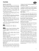
Sequence of operation
Electro-mechanical controls — A 24-v signal from the
thermostat to terminal G supplies power to the blower
motor(s), condensate pump and vane motor (if equipped).
A toggle switch on the control box can be used to switch
the oscillating vanes on or off. The condensate pump will
run continuously, as long as the blower is energized. A call
for heating, at terminal W, or cooling, at terminal Y, will
energize the water valve actuator and allow water to flow
through the cassette coil. When the call for heating or cool-
ing is satisfied the valve will close.
If the temperature drops below the set point of the coil
freezestat, the water valve with automatically open to circu-
late water through the coil.
If the condensate float switch detects a high level of
water in the condensate tray, the switch will open, activate
the condensate pump and disable the heating/cooling sig-
nal until the water level drops down to normal.
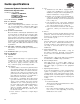
Microprocessor controls — The PCB (printed circuit
board) microprocessor control board relays control the
operation of the indoor-fan motor, outdoor-fan motor,
compressor and electric heater (if fitted), to maintain room
conditions at a user-defined set point.
Temperature settings, fan speeds and other control
functions can be changed by the infrared transmitter or
optional pendant. The controller PCB provides the follow-
ing input/output facilities:
Inputs
T1 Return Air Temperature Sensor: 50k at 77 F.
T3 Indoor Coil Temperature Sensor: 50k at 77 F.
Outputs
Indoor fan motor — The controller will switch a combina-
tion of three, 10-amp, 230-vac (3 speed settings) resistive
rated relays to deliver the selected indoor fan speed.
Condensate pump — Activated when unit is in cooling
mode.
Vane motor — A 10-amp, 230-vac resistive rated relay
switches the vane motor on when Air Sweep is selected
(units sizes 18-36 only).
Electric heat — A 30-amp, 230-vac resistive rated relay
switches the electric heater on when required.
Indoor fan operation
The indoor fan will run continuously at the most recently
set speed or will alter the speed according to the room
temperature conditions when set to Auto. The indoor fan
will continue to run until the unit is turned off by the user or
by a preset time setting. When the unit is turned off during
heating, the indoor fan will continue to run for approxi-
mately 2 minutes, this helps to dissipate residual heat from
the electric heaters.
Boost heat
The electric heat relay can be used to initiate either low
watts density electric heating (optional) or low pressure hot
water heating (optional). The boost heat will be activated
when the room temperature falls to more than 8º F below
set point. Hysteresis of 2º F will be applied to prevent
“hunting.” The boost heat facility is automatically enabled
or disabled by selecting non heat pump (Jumper 2 open).
Temperature control
The controller will switch heating or cooling loads in order
to maintain the temperature set point. The deadband is
programmed to 4º F. Under normal operation, cooling or
heating will be activated at the limits of the deadband and
will continue to operate until set point is achieved.
The temperature set point can be adjusted between
58 and 90 F in 2º F increments.
Power failure
The controller will auto restart in its previous mode of
operation after a power failure. When power is restored,
the controller will revert to its last operating mode, e.g., if
the controller was turned on before power fail, after power
is restored the controller will automatically turn on. Alter-
natively, if the controller was turned off before power fail,
the controller will remain off after power is restored.
Electric heater overheat protection
In the event of an auto reset overheat cutout, the electric
heater will be switched off until the temperature drops suf-
ficiently for the auto cutout to reset itself.
Master/slave operation
The network option allows for one master unit and up to
19 slave units to be interconnected using a twin twisted
pair screened cable to create a network.
The master/slave operation has been programmed to
operate the units in the following manner:
When the master unit receives a transmission from the
transmitter, the transmitter settings are provided to all units
on the network.
Slave units do NOT monitor the return-air temperature
but rely instead on the master unit to monitor return-air
temperature and make all control decisions. Slave units will
mimic the operation of the master unit and will cool, heat,
switch on, switch off etc., with the master.
At all times, the slave units will follow the usual method
of operation regarding alarms and will act accordingly.
When a master unit experiences an alarm, it will act in the
usual manner while maintaining instruction to slave units to
operate normally. The exception to this is when the master
unit experiences a return air sensor failure. Because the
master unit cannot control correctly, it will instruct the
slave units to revert to stand-alone operation.
In the event of the network cable being severed or com-
munications between master and slaves being lost for any
reason, the slave units will revert to stand-alone control
after six minutes without instruction from the master. Dur-
ing this time, the slaves will monitor the return air tempera-
ture themselves and will make their own control decisions
based upon the last set of transmitter settings received
from the master unit.
Controls