AQUAFORCE® 30XA080-500 Air-Cooled Liquid Chillers Controls, Start-Up, Operation, Service and Troubleshooting CONTENTS Page SAFETY CONSIDERATIONS . . . . . . . . . . . . . . . . . . . . .2,3 GENERAL . . . . . . . . . . . . . . . . . . . . . . . . . . . . . . . . . . . . . . 3-8 Conventions Used in This Manual . . . . . . . . . . . . . . . . 3 Display Module Usage . . . . . . . . . . . . . . . . . . . . . . . . . . . 3 • TOUCH PILOT™ DISPLAY • NAVIGATOR™ DISPLAY MODULE CONTROLS . . . . . . . . . . . . . . .
Page CONTENTS (cont) APPENDIX F — MAINTENANCE SUMMARY AND LOG SHEETS. . . . . . . . . . . . . . . . . . . . . . . . . . 165-167 APPENDIX G — BACNET COMMUNICATONS OPTION . . . . . . . . . . . . . . . . . . . . . . . . . . . . . . . . . . . . . 168-178 Page SERVICE . . . . . . . . . . . . . . . . . . . . . . . . . . . . . . . . . . . . . 74-87 Economizer Assembly. . . . . . . . . . . . . . . . . . . . . . . . . . . 74 Electronic Expansion Valve (EXV) . . . . . . . . . . . . . . .
configuration. The user would scroll through the modes and sub-modes using the and keys on the Navigator display. For the Touch Pilot display, the user would simply touch the menu item on the screen. The arrow symbol in the path name represents pressing ENTER to move into the next level of the menu structure for the Navigator module, or touching the menu item on the screen for the Touch Pilot display. CAUTION This unit uses a microprocessor-based electronic control system.
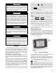
with up to 9 points on 8 separate screens. For more information on adding or removing points from the Group Display screen, see the Group Display Screens section on page 6. Touch any of the screen point buttons and Point Data Dialog box will be displayed with expanded information. In the example shown below, the CTRL_PNT button in the bottom left corner was selected. See Fig. 2 and 3. To exit the box, press . Main Menu Display — The default screen for the Touch Pilot controller is the Group Display screen.
a30-4474 Fig. 4 — Main Menu Display a30-4472 Fig.
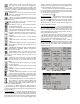
Table 1 — Setup Menu SETUP MENU BUTTON REGIONAL LANGUAGE CONTRAST BACKLIGHT CALIBRATE FUNCTION This button specifies the time and date format and the base unit of measure. Time display can be configured as 12hour AM/PM setting or as a 24-hour setting. The date can be formatted in one of 3 settings, MM-DD-YYYY (MonthDay-Year), DD-MM-YYYY (Day-Month-Year), or YYYY-MM-DD (Year-Month-Day). Units of measure can be either US (English) or Metric (SI).
display will be shown. If communication is not established, the Navigator module will display: Communication Failure If the Navigator module is connected to a Main Base Board without software loaded, the display will remain at the powered-up initialization display. Setting the Time and Date — The ComfortLink control has a time and date function. This can be useful for diagnostics to determine when alarms occur. The control is factory configured for the proper date and for use in the Eastern Time Zone.
Table 2 — ComfortLink™ Navigator™ Display Menu Structure RUN STATUS Auto Display (VIEW) Machine Starts/Hours (RUN) Compressor Run Hours (HOUR) Compressor Starts (STRT) Fan Run Hours (FAN) MODE SERVICE SET TEMPERATURES PRESSURES INPUTS OUTPUTS CONFIGURATION TEST POINTS Manual Unit Circuit A Cooling General Circuit A Display Test Mode Temperatures Pressures Setpoints Inputs Outputs Configuration (TEST) (UNIT) (PRC.A) (COOL) (GEN.I) (CIR.
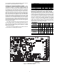
For a complete description of Main Base Board inputs and outputs and their channel identifications, see Table 3. Compressor Protection Module (CPM) — There is one CPM per compressor. See Fig. 9. The device controls the compressor contactors, oil solenoid, loading/unloading the solenoid, motor cooling solenoid (30XA080,082 only) and the oil separator heater.
Table 3 — Main Base Board Inputs and Outputs DESCRIPTION INPUT/OUTPUT I/O TYPE DISPLAY MODULE POINT NAME Power (24 vac supply) — — — Local Equipment Network — — — Carrier Communication Network — — — Chilled Water Flow Switch CWFS Switch Cooler Flow Switch, LOCK Demand Limit Switch No. 1 Demand Limit SW1 Switch Limit Switch 2 Status, DLS1 Circuit A Discharge Pressure Transducer DPTA Pressure Transducer Discharge Pressure, DP.
DIP SWITCH 2 (S2) C CH 06 C CH 10 CH 12 CH 11 R R CH02 CH01 DG MOT TMP J9 TMP J11 J2 CH 05 CH 13 CH 14 12 11 J10B J10A R S 5 CH03 R SMT S 5 CH04 OIL PRESS LOADERS OLS MOTOR COOLING 151 1 R20 ECO AUX PRESS 2 2 151 24 VDC/OLL 151 HPS 151 2x 151 2x 151 561 DIP SWITCH 3 (S3) 561 561 561 151 102 151 151 151 102 620 0N 102 102 102 1 2 3 4 101 S3 CT1 CT2 LOCATION OF SERIAL NUMBER MTA K40 0N CT3 1 2 3 4 5 6 7 8 S2 J8 K40 0N S1 1 2 3 4 5 6 7 8 151 151 J4 1
Table 5 — Compressor Protection Module Inputs and Outputs* DESCRIPTION INPUT/OUTPUT I/O TYPE DISPLAY MODULE POINT NAME Power (24 vac supply) — — — Local Equipment Network — — — Circuit X High Pressure Switch HPS-X Switch Not available CONNECTION POINT Pin Notation CPM-X-J1 11 24 vac 12 Ground CPM-X-JP12 1 RS485 Port (D+) 2 RS485 Port (Gnd) 3 RS485 Port (D-) CPM-X-J12 1 RS485 Port (D+) 2 RS485 Port (Gnd) 3 RS485 Port (D-) CPM-X-J7-CH05 1 2 CPM-X-J6-CH06 Oil Level Switch Oil LS X Switch Ci
COMM J4 3 2 1 - G + 1 U2 SB Q7 S1 ON 1 D15 C10 5 U6 THB 2 L1 3 U1 4 C37 712 D2 THA C39 J3 R9 Q4 C11 Q5 C25 TEMP 100 D1 C49 100K 4 Q12 Q17 Q15 Q20 Q22 Q27 Q25 6 2 5 Q10 7 1 J2B 3 3 4 EXVB 2 257-01 D8 2 J2A D9 3 4 EXVA 5 8 D29 SI0 (LEN) STATUS 1 DIP SWITCH R2 L3 100 L2 100 100K R3 Q30 Q2 Q1 L4 U5 G2 U4 Q37 Q42 Q35 Q45 D5 + C16 C15 D6 D4 LOCATION OF SERIAL NUMBER C17 MOV1 J1 24VAC 12/11 a30-4216 Fig.
Table 6 — EXVA Board Inputs and Outputs (30XA080,082) DESCRIPTION INPUT/OUTPUT I/O TYPE DISPLAY MODULE POINT NAME Power (24 vac supply) — — — Local Equipment Network — — — Circuit A Suction Gas Thermistor SGTA 5k Thermistor Compressor Suction Temp, SGT.A Circuit B Suction Gas Thermistor SGTB 5k Thermistor Compressor Suction Temp, SGT.B Circuit A EXV EXV-A Stepper Motor EXV Position, EXV.A Circuit B EXV EXV-B Stepper Motor EXV Position, EXV.
Fan Boards — At least one fan board is installed in each unit. See Fig. 11 and 12. There are two types of fan boards. One with and one without an analog output signal for the low ambient temperature head pressure control fan speed controllers. If a unit does not have low ambient temperature head pressure control installed, it will not have the analog connection terminals.
Table 8 — Fan Board A Outputs (30XA080-122) DESCRIPTION INPUT/OUTPUT I/O TYPE DISPLAY MODULE POINT NAME Power (24 vac supply) — — — Local Equipment Network — — — Circuit A Low Ambient Temperature Head Pressure Control Speed Signal MM-A* 0-10 VDC Head Press Actuator Pos, SPD.A Circuit B Low Ambient Temperature Head Pressure Control Speed Signal MM-B* 0-10 VDC Head Press Actuator Pos, SPD.
Table 10 — Fan Board C Inputs and Outputs (30XA400-500) CONNECTION POINT (Unit Size) Pin Notation FBC-J1 11 24 vac 12 Ground FBC-J9 + RS485 Port (D+) G RS485 Port (Gnd) RS485 Port (D-) + RS485 Port (D+) G RS485 Port (Gnd) RS485 Port (D-) DESCRIPTION INPUT/OUTPUT I/O TYPE DISPLAY MODULE POINT NAME Power (24 vac supply) — — — Local Equipment Network — — — Circuit C Discharge Pressure Transducer Circuit C Suction Pressure Transducer DPTC Pressure Transducer Discharge Pressure, DP.
Table 11 — Energy Management Module (EMM) Inputs and Outputs INPUT/OUTPUT 4-20 mA Demand Limit 4-20 mA Temperature Reset/Cooling Setpoint Demand Limit SW2 Ice Done Occupancy Override Remote Lockout Switch SPT % Total Capacity RUN R SHD R DESCRIPTION 4-20 mA Demand Limit 4-20 mA Temperature Reset/ Cooling Set point Demand Limit Step 2 Ice Done Switch Occupied Schedule Override Chiller Lockout Space Temperature Thermistor Percent Total Capacity Output Run Relay Shutdown Relay I/O TYPE 4-20 mA* 4-20 mA* DIS
Table 12 — Hot Gas Bypass/Pump Board Inputs and Outputs CONNECTION POINT DESCRIPTION INPUT/OUTPUT I/O TYPE DISPLAY MODULE POINT NAME — — — — — — MLV-A MLV-B MLV-C PMP1 PMP2 Solenoid Valve Solenoid Valve Solenoid Valve Contactor Contactor Hot Gas Bypass A Output, HGB.A Hot Gas Bypass B Output, HGB.B Hot Gas Bypass C Output, HGB.C Water Exchanger Pump 1, PMP.1 Water Exchanger Pump 2, PMP.
It is important when connecting to a CCN communication bus that a color-coding scheme be used for the entire network to simplify the installation. It is recommended that red be used for the signal positive, black for the signal negative, and white for the signal ground. Use a similar scheme for cables containing different colored wires. At each system element, the shields of its communication bus cables must be tied together.
Fig. 16 — ComfortLink™ CCN Communication Wiring Service Tool or ComfortVIEW™ software. The tables are the CtrlID (Controller Identification) configuration table and the USERCONF (User Configuration) table. See Tables 15 and 16. NOTE: Always perform an Upload to obtain the latest configuration before making configuration table changes.
such as ComfortVIEW™ software, the Autodial Gateway or TeLINK is already set as the alarm acknowledger for the CCN network then this decision should be set to No. NOTE: The display must be in Network mode and connected to the primary CCN bus and this decision set to Yes for alarm acknowledgement to be enabled. Allowable Entries: No Yes Default Value: No BROADCAST ACKNOWLEDGER — This configuration is used to indicate whether the Touch Pilot display will act as the broadcast acknowledger for its CCN bus.
Control Type will be Local. The Operating Type variable will change to L-Sched (Local Schedule). The schedules consist of 8 user-configurable occupied time periods. The control supports time schedules for local control, remote control, and ice building. These time periods can be flagged to be in effect or not in effect on each day of the week. The day begins at 00.00 and ends at 24.00. The machine will be in unoccupied mode unless a scheduled time period is in effect.
Table 19 — Programming Holiday Schedules with Touch Pilot Display LINE NO. VALUE Holiday Start Month 1 7 Start Day Config\HOLIDAY\HOLDY_01 2 4 Duration (days) 3 1 Holiday Start Month 1 12 Start Day Config\HOLIDAY\HOLDY_02 2 25 Duration (days) 3 2 DISPLAY NAME PATH Timed Override — With the Touch Pilot display only, each time schedule can be overridden to keep the chiller in an Occupied mode (Timed Override Hours) for 1, 2, 3 or 4 hours on a one-time basis.
displayed. Select Remote Mode. The unit will be controlled by the Enable/Off/Remote Contact switch. Switching the Enable/ Off/Remote Contact switch to the Enable or Remote Contact position (external contacts closed) will force the unit into an occupied state. In this mode, all CCN network force commands, except the Emergency Stop Command will be ignored.
Two Internal Time Schedules are available and must be field programmed. Time Schedule 1 (SCH1) is used for single set point On-Off control. Time Schedule 2 (SCH2) is used for dual set point On-Off and Occupied-Unoccupied set point control. The control will use the operating schedules as defined under the Time Clock mode in the Navigator display module. ITEM ITEM EXPANSION PATH Operating Control Operating OPER Type ModesSLCTOPER Table 22 — Configuring Schedules with Navigator™ Display ITEM OCC.1 UNO.
To configure this option for the Navigator™ display: The Occupancy Supervisory Part table name (OCC1P01S) number must be changed to configure the unit to broadcast a Global Time Schedule. The Schedule Number can be set from 65 to 99 (OCC1P65S to OCC1P99S). When OCC1PxxS is set to a value greater than 64, an occupancy flag is broadcast over the CCN every time it transitions from occupied to unoccupied or vice-versa.
The following equation is used to control the set point. See Fig. 20. Fahrenheit Set Point = 10 + 70(mA – 4)/16 (deg F) Celsius Set Point = –12.2 + 38.9(mA – 4)/16 (deg C) To configure this option while using a Touch Pilot display: Set Point 1 (Cooling Setpoint 1, CSP.1) during the occupied period while operating under Time Schedule 1 (SCH1). If the Time Schedule 2 (SCH2) is in use, the unit’s active set point is based on Cooling Set Point 1 (Cooling Setpoint 1, CSP.
90 80 70 Max LWT Set Point 60 50 Min LWT, Cooler Fluid Type = 1, FLUD=Water 40 30 20 Min LWT, Cooler Fluid Type = 1, FLUD=Brine 10 0 0 2 4 6 8 10 12 14 16 18 20 a30-4476 mA Signal Fig.
When Cooler Pumps Sequence is set to 0 (No Pump), closure of both the chilled water flow switch (CWFS) and the chilled water pump interlock contact (connected across TB-5 terminals 1 and 2) are required for the unit to start mechanical cooling. To configure this option with the Touch Pilot™ display: BRINE OR GLYCOL OPERATION — Configure the unit for Cooler Fluid Type (Cooler Fluid Type, FLUD) to brine for brine or glycol chilled water loops.
To configure these options with the Touch Pilot™ display: To configure this option with the Navigator display: ITEM ITEM EXPANSION PATH VALUE PUMP Cooler Pumps ConfigurationOPTN 1 Pump Only Sequence Default = No Periodic Pump PM.PS Start ConfigurationOPTN No = Disabled Yes = Enabled Default = Yes Flow Checked P.LOC if Pmp Off ConfigurationOPTN No = Disabled Yes = Enabled LINE NO.
To configure this option with the Navigator display: To configure this option with the Touch Pilot display: DISPLAY NAME LINE NO. PATH VALUE ITEM 0 (Automatic Lead-lag) 1 (Circuit A Leads) 2 (Circuit B Leads) 3 (Circuit C Leads) Default = 0 (Automatic Lead-lag) Circuit Loading Main Menu Sequence ConfigUSER 1 ITEM EXPANSION Lead/Lag LLCS Circuit Select PATH Configuration OPTN available for the control of two units installed in series or parallel supplying chilled fluid on a common loop.
Lead Compressor Loading Lag Compressor Loading Lead Compressor Unloading Lag Compressor Unloading Lead compressor can fall anywhere in this area when load between 40%~65% 100 Compressor Capacity (%) 80 UNLOADING LOADING 60 40 20 Lag compressor can fall anywhere in this area when load between 40%~65% 0 100 0 0 Load (%) a30-4466 Equal Circuit Loading Compressor Loading Unloading (Staged circuit loading) Lead Compressor Loading Lag Compressor Loading 100 Lead Compressor Unloading Lag Compressor
Table 28 — Dual Master Chiller Control Parameters for Parallel Applications with Touch Pilot™ Display DISPLAY NAME PATH LINE NO.
Table 30 — Dual Slave Chiller Control Parameters for Parallel Applications with Touch Pilot™ Display DISPLAY NAME PATH LINE NO.
DUAL CHILLER CONTROL FOR SERIES APPLICATIONS — To configure the master chiller for series applications using the Touch Pilot™ display, see Table 32. To configure the master chiller for series applications using the Navigator™ display, see Table 33. To configure the slave chiller for series applications using the Touch Pilot™ display, see Table 34. To configure the slave chiller for series applications using the Navigator™ display, see Table 35. A power cycle is required for the values to take effect.
Table 34 — Dual Slave Chiller Control Parameters for Series Applications with Touch Pilot Display DISPLAY NAME PATH LINE NO.
Under normal operation, the chiller will maintain a constant entering or leaving fluid temperature, based on the configuration, approximately equal to the chilled fluid set point. As the cooler load varies, the cooler fluid temperature difference will change in proportion to the load. For example, if the chiller was selected for a Entering to Leaving Water Temperature difference of 10 F (5.5 C) at full load, at 50% load the temperature difference would be 5 F (2.2 C). See Fig. 22.
56 54 Fluid Temperature (deg F) 52 EWT 50 Design Rise (typical) 48 46 LWT 44 42 40 0 10 20 30 40 50 60 70 80 90 100 a30-4066 % Load Fig. 22 — Leaving Chilled Water Temperature Control 56 EWT 54 Fluid Temperature (deg F) 52 50 Design Rise (typical) LWT 48 46 44 42 40 0 10 20 30 40 50 60 70 80 90 100 a30-4478 % Load Fig.
To use Space Temperature Reset, four variables must be configured. Cooling Reset Type (Cooling Reset Select, CRST) must be enabled. The space temperature at which no temperature reset is required, Space T No Reset Temp (Space T No Reset Value, CRS1) must be set. The space temperature at which full temperature reset is required, Space T Full Reset Temp (Space T Full Reset Value, CRS2) must be set. Finally, the amount of temperature reset desired, Degrees Cool Reset (Cooling Reset Deg.
6 5 Degrees Reset (deg F) 4 Cooling Reset Deg. Value, DGRC 3 Delta T No Reset Temp, CRT1 2 Delta T Full Reset Temp, CRT2 1 0 2 0 6 4 8 10 a30-4479 Entering-Leaving Water Temperature (deg F) Fig. 24 — Return Water Reset 16 14 Reset Amount (deg F) 12 10 Cooling Reset Deg. Value, DGRC 8 6 OAT No Reset Value, CRO1 OAT Full Reset Value, CRO2 4 2 0 0 20 40 60 80 Outdoor Temperature Fig.
7 6 Degrees Reset (deg F) 5 4 Cooling Reset Deg. Value, DGRC 3 Space T No Reset Value, CRS1 2 Space T Full Reset Value, CRS2 1 0 60 65 70 75 Space Temperature (deg F) 80 a30-4481 Fig. 26 — Space Temperature Reset To configure this option with the Touch Pilot™ display: DISPLAY NAME LINE NO. PATH Cooling Reset Select ConfigUSER Main Menu Current No Reset Value Current Full Reset Value Cooling Reset Deg.
6 5 Degrees Reset (deg F) 4 Cooling Reset Deg. Value (DGRC) 3 Current No Reset Value (CRV1) 2 1 Current Full Reset Value (CRV2) 0 0 10 5 15 20 a30-4482 mA Signal Fig. 27 — 4 to 20 mA Temperature Reset capacity to 40%. Demand Limit Switch 1 is 60% and Demand Limit Switch 2 is 40%. Switch Controlled (Capacity Based) — If using 2-step Demand Limit control, an Energy Management Module must be installed. One-step Demand Limit control does not require the Energy Management Module.
20 mA signal is connected to TB6-1 and TB6-2. The demand limit is a linear interpolation between the two values entered. In Fig. 28, if the machine receives a 12 mA signal, the machine controls will limit the capacity to 50%. EXTERNALLY POWERED (4 to 20 mA) CURRENT BASED DEMAND LIMIT — The Energy Management Module is required for 4 to 20 mA demand limit control. An externally powered 4 to 20 mA signal must be connected to TB6-1 and TB6-2.
100 90 80 % Demand Limit 70 60 mA For 0% Demand Limit, DMZE 50 40 30 mA For 100% Demand Limit, DMMX 20 10 0 2 0 4 6 8 10 12 14 16 18 mA Demand Limit Signal 20 a30-4483 Fig. 28 — 4 to 20 mA Demand Limit (Capacity) 2000 1800 1600 Compressor Current 1400 1200 mA For 0% Demand Limit, DMZE 1000 80 0 60 0 mA Fo r 100% Demand Limit, DMMX 40 0 20 0 0 0 2 4 6 8 10 12 14 16 mA Signal Fig.
To configure this option with the Touch Pilot display: CCN LOADSHED CONTROLLED DEMAND LIMIT — To configure Demand Limit for CCN Loadshed control, the unit Operating Type Control must be in CCN control. With the Touch Pilot™ display, the machine must be started with CCN Control. For the Navigator™ display, the Operating Control Type (I/O Button, OPER) must be CCN CONTROL. The unit must be controlled by a Chillervisor module.
DESCRIPTION Alarm Routing 0 0 0 STATUS 0 0 0 0 0 POINT ALRM_CNT ComfortView™, or ComfortWorks® TeLink Unused BacLink or DataLink™ Unused a30-4485 Fig. 30 — Alarm Routing Control characters in length. This variable can only be changed when using the Touch Pilot display, ComfortVIEW, or Network Service Tool. This variable cannot be changed with the Navigator display.
operating modes. See Table 37 for a list of overrides. See the Operating Modes section on page 68 for more information regarding operating modes. Override #1: Cooler Freeze Protection — This override attempts to avoid the freeze protection alarm. If the Leaving Water Temperature is less than Brine Freeze Set Point (Brine Freeze Setpoint, LOSP) + 2.0° F (1.1º C) then a stage of capacity is removed. NOTE: The freeze set point is 34 F (1.1 C) for fresh water systems (Cooler Fluid Type, FLUD=1).
freeze set point is Brine Freeze Set Point (Brine Freeze Setpoint, LOSP), for Medium Temperature Brine systems (Cooler Fluid Type, FLUD=2). If any of these conditions are met, the appropriate operating mode, 21 (Circuit A), 22 (Circuit B) or 23 (Circuit C) will be in effect. Override #26: Circuit A High Discharge Gas Override Override #27: Circuit B High Discharge Gas Override Override #28: Circuit C High Discharge Gas Override — When the temperature is above the limit curve minus 2° F (1.
Override #77: Boostload Function — This override can be present when boostload function is enabled. It is set in the following conditions : if cool_lwt > ctrl_pnt + 5.4 and cool_ewt > ctrl_pnt + 9.0 and demand limit > 99%. capacity will be held at current capacity. If the compressor current is greater than 85% MTA then capacity will be reduced by repositioning the slide valve until the current is less than 85% MTA (Must Trip Amps, MTA.X).
CIRCUIT STAGE CIRCUIT Fan stage A COMP B FM1 COMP A FM3 FM2 A FM5 FM4 FM6 B 30XA080,082 COMP B COMP A A FM1 FM3 FM5 FM7 FM2 FM4 FM6 FM8 B 30XA090-122 COMP B COMP A PEB A 3 Contactor # FC B1 FC B2 FC B3 Fan position FM1 FM4 FM2 Fan stage A 1 2 3 Contactor # Fan position FM7 FM5 FM8 FM6 Fan stage B 1 2 3 4 Contactor # FC B1 FC B2 FC B3 FC B4 Fan position FM1 FM3 FM2 FM4 Fan stage A 1 2 3 4 Contactor # Fan position FM9 FM7 FM5 FM10 FM10 Fan stage
CIRCUIT STAGE CIRCUIT Fan stage A A COMP B PEB A/B COMP A FM3 FM5 FM7 FM9 FM11 FM13 FM15 FM17 FM19 FM2 FM4 FM6 FM8 FM10 FM12 FM14 FM16 FM18 FM20 a30-4219 B 30XA400 C a30-4220 PEB A/B COMP A PEB C A COMP C FM1 FM3 FM5 FM7 FM9 FM11 FM13 FM15 FM17 FM19 FM21 FM2 FM4 FM6 FM8 FM10 FM12 FM14 FM16 FM18 FM20 FM22 B 30XA450, 500 a30-4221 COMP — FC — 2 3 4 5 6 FC A1 FC A2 FC A3 FC A4 FC A5 FC A6 Fan position FM11 FM9 FM7 FM12 FM10 FM8 Fan stage B 1 2 3 4 5 6 7
Table 39 — Siemens VFD Control Parameters PARAMETER* P0010 P0311 P0757 P0761 P3900 P0003 P1210 P1310 VALUE 1 1140† 850** 0.50 0.
13. The drive is now active. Check fan rotation prior to testing. If the fan is spinning forward, further adjustment is needed. Fan should sit still when commanded speed is 0%. If the fan is spinning forward slightly, press P and to Parameter P0761. Press P and use to change this value to 0.1. Press P to accept. Check the fan. If rotation has stopped no further adjustment is required. If the fan is still rotating forward, press P and use to change this value to 0.2. Press P to accept.
Table 40 — Siemens Low Ambient Temperature Controller Operator Panel PANEL/BUTTON FUNCTION DESCRIPTION Indicates Status The LCD displays the settings currently used by the converter. Start Converter The Start Converter button is disabled by default. To enable this button set P0700 = 1. Stop Converter Press the Stop Converter button to cause the motor to come to a standstill at the selected ramp down rate. Disabled by default, to enable set P0700 = 1.
P0010 Start Quick Commissioning 0 Ready to Run 1 Quick Commissioning 30 Factory Setting NOTE: P0010 must always be set back to ‘0’ before operating the motor. However if P3900 = 1 is set after commissioning this is done automatically.
Table 41 — Siemens Low Ambient Temperature Controller Fault Messages FAULT F0001 Overcurrent F0002 Overvoltage F0003 Undervoltage F0004 Drive Overtemperature F0005 Drive I2t F0011 Motor Overtemperature I2t F0041 Stator Resistance Measurement Failure F0051 Parameter EEPROM Fault F0052 Powerstack Fault F0060 Asic Timeout F0070 Communications Board Set Point Error F0071 No Data for RS232 Link During Telegram Off Time F0072 No Data from RS485 Link During Telegram Off Time F0080 Analog Input Lost Input Sign
Table 42 — Siemens Low Ambient Temperature Controller Alarm Messages FAULT A0501 Current Limit POSSIBLE CAUSES • Motor power does not correspond to the drive power • Motor leads are too short • Ground fault A0502 Overvoltage Limit A0503 Undervoltage Limit A0504 Drive Overtemperature A0505 Drive I2t A0506 Drive Duty Cycle A0511 Motor Overtemperature I2t A0541 Motor Data Identification Active A0600 RTOS Overrun Warning • Mains supply too high • Load regenerative • Ramp-down time too short • Mains supply t
Table 43 — Schnieder Altivar 21 VFD Operating Parameters PARAMETER uLu F201 F202 F203 F204 F401 F415 F417 F701 tHr uL FH LL UL ACC dEC cnod fnod NAME Rated Motor Voltage VIA Speed Reference Level 1 VIA Output Frequency Level 1 VIA Speed Reference Level 2 VIA Output Frequency Level 2 Slip compensation Rated Motor Current Rated Motor Speed Keypad display: % or A/V Motor Rated Current Overload Setting Rated Motor Frequency Maximum Frequency Low Speed High Speed Ramp-up Time Ramp-down Time Remote Mode Start/St
1. Determine average voltage: Operating Limitations TEMPERATURES — Unit operating temperature limits are listed in the table below. TEMPERATURE Maximum Ambient Temperature Minimum Ambient Temperature Maximum Cooler EWT* Maximum Cooler LWT Minimum Cooler LWT† F 125 32 95 60 40 Average voltage = C 52 0 35 15 4.4 = = 2. Determine maximum deviation from average voltage: (AB) 243 – 239 = 4 v (BC) 239 – 236 = 3 v (AC) 239 – 238 = 1 v Maximum deviation is 4 v. 3.
Table 44 — 30XA Minimum and Maximum Cooler Flow Rates 30XA UNIT SIZE 80 82 90 92 100 102 110 112 120 122 140 142 160 162 180 182 200 202 220 222 240 242 260 262 280 282 300 302 325 327 350 352 400 450 500 DX ITEM Cooler Leaving Water Temperature* Cooler Entering Water Temperature† Nominal Flow Rate Cooler (gpm) (L/s) Standard, Flooded 180.4 11.4 Plus One Pass, Flooded Minus One Pass, Flooded 172.8 10.9 DX Cooler Standard, Flooded 201.9 12.7 Plus One Pass, Flooded Minus One Pass, Flooded 193.7 12.
Unit Sizes 30XA080, 90, 100, 110, 120 50 (149.5) 080 45 (134.6) 090,100 110 120 Pressure Drop, ft wg (kPa) 40 (119.6) 35 (104.7) 30 (89.7) 25 (74.8) 20 (59.8) 15 (44.9) 10 (29.9) 5 (15) 0 0 100 (6.3) 200 (12.6) 300 (18.9) 400 (25.2) 500 (31.6) Cooler Flow, GPM (l/s) 600 (37.9) a30-4233 Unit Sizes 30XA140, 160, 180, 200, 220, 240 60 (179.4) 240 160 Pressure Drop, ft wg (kPa) 220 140 50 (149.5) 180 200 40 (119.6) 30 (89.7) 20 (59.8) 10 (29.9) 0 0 200 (12.6) 400 (25.2) 600 (37.
Unit Sizes 30XA260, 280, 300, 325, 350, 400, 450, 500 60 (179.4) 260 280 300 Pressure Drop, ft wg (kPa) 50 (149.5) 325 350 500 450 40 (119.6) 400 30 (89.7) 20 (59.8) 10 (29.9) 0 500 (31.6) 0 1000 (63.1) 1500 (94.6) 2000 (126.2) 2500 (157.7) 3000 (189.3) a30-4257 Cooler Flow, GPM (l/s) Fig. 38A — Cooler Pressure Drop Curves, Standard Pass Flooded Cooler (cont) Unit Sizes 30XA082, 092, 102, 112, 122, 142, 162, 182, 202 70 (209.3) Pressure Drop, ft wg (kPa) 60 (179.
Unit Sizes 30XA222, 242, 262, 282, 302, 327, 352 80 Pressure Drop, wg (kPa) (239.1) 60 (179.4) 222, 242 302, 327, 352 262, 282 40 (119.6) 20 (59.8) 0 0 200 (12.62) 400 (25.24) 600 (37.85) 800 (50.47) 1000 (63.09) 1200 (75.71) 1400 (88.32) 1600 (100.94) 1800 (113.56) Cooler Flow, GPM (l/s) Fig.
Unit Sizes 30XA140, 160, 180, 200, 220, 240 250 (747) 180 200 (598) 200 Pressure Drop, ft wg (kPa) 220 140 240 160 150 (488) 100 (299) 50 (149) 0 0 200 (12.6) 400 (25.2) 600 (37.9) a30-4487 800 (50.6) 1000 (63.3) 1200 (75.9) 1400 (88.6) COOLER FLOW, GPM (l/s) Unit Sizes 30XA260, 280, 300, 325, 350 250 (747) 280 200 (598) 260 Pressure Drop, ft wg (kPa) 300 325 350 150 (488) 100 (299) 50 (149) 0 0 a30-4489 200 (12.6) 400 (25.2) 600 (37.9) 800 (50.6) 1000 (63.3) 1200 (75.
Unit Sizes 30XA080, 090, 100, 110, 120, 140 10 (29.9) 9 (26.1) 140 Pressure Drop, ft wg (kPa) 8 (23.2) 080 110 090,100 120 7 (20.3) 6 (17.4) 5 (14.5) 4 (11.6) 3 (8.7) 2 (5.8) 1 (2.9) 0 0 100 (6.3) 200 (12.6) 300 (18.9) 400 (25.2) 500 (31.6) 600 (37.9) 700 (44.2) COOLER FLOW, GPM (l/s) a30-4490 Unit Sizes 30XA140, 160, 180, 200, 220, 240 12 (35.7) 160 10 (29.9) 140 Pressure Drop, ft wg (kPa) 240 220 8 (23.2) 200 180 6 (17.4) 4 (11.6) 2 (5.3) 0 0 200 (12.6) 400 (25.2) 600 (37.
Unit Sizes 30XA260, 280, 300, 325, 350 10 (29.9) 350 325 280 9 (26.1) 300 260 8 (23.2) Pressure Drop, ft wg (kPa) 7 (20.3) 6 (17.4) 5 (14.5) 4 (11.6) 3 (8.7) 2 (5.5) 1 (2.9) 0 0 200 (12.6) 400 (25.2) 600 (37.9) 800 (50.6) 1000 (63.3) 1200 (75.9) 1400 (88.6) 1600 (101.3) 1800 (114.0) a30-4492 COOLER FLOW, GPM (l/s) NOTE: Minus-one-pass coolers are not available for 30XA400-500 units. Fig.
Dual Chiller Sequence of Operation — With a com- mand to start the chiller, the master chiller determines which chiller will become the lead chiller based on the configuration of Lead Lag Select, LLBL and Lead/Lag Balance Data, LLBD. The lead chiller is always started first and the lag chiller is held at zero percent capacity by the master chiller forcing the lag demand limit value to 0%.
Table 45 — 30XA Operating Modes NAVIGATOR OPERATING MODE NUMBER 01 02 03 04 05 06 07 08 09 10 11 12 13 14 15 16 17 18 19 20 21 22 23 24 25 26 27 28 29 30 31 32 NAVIGATOR EXPANSION Startup Delay in Effect Second Setpoint in Use Reset in Effect Demand Limit Active Ramp Loading Active Cooler Heater Active Cooler Pumps Rotation Pump Periodic Start Night Low Noise Active System Manager Active Mast Slave Ctrl Active Auto Changeover Active Free Cooling Active Reclaim Active Electric Heat Active Heating Low EWT Lo
Setpoint (CSP.3). This mode will terminate when the Ice Setpoint (CSP.3) is no longer in use. DEFROST ACTIVE ON CIR A — This mode is not supported. DEFROST ACTIVE ON CIR B — This mode is not supported. LOW SUCTION CIRCUIT A LOW SUCTION CIRCUIT B LOW SUCTION CIRCUIT C — These modes are checked when the circuit is ON. The appropriate circuit mode will be active if one of the following conditions is true: 1. If the circuit’s saturated suction temperature (SST) is more than 6° F (3.
the conditioned space where it will not be subjected to either a cooling or heating source or direct exposure to sunlight, and 4 to 5 ft above the floor). Space temperature sensor wires are to be connected to terminals in the unit main control box. See Fig. 44. The space temperature sensor includes a terminal block (SEN) and a RJ11 female connector. The RJ11 connector is used access into the Carrier Comfort Network® (CCN) at the sensor. To connect the space temperature sensor (see Fig. 44): 1.
O-RING BRASS NUT 3/8 - 24 FOR ASSEMBLY ON BRASS WELL a30-4079 Fig. 42 — 5K Thermistor (Sensor 00PPG000008105A, Connector: HY06AM016) 1/4-18 NPT a30-4080 SENSOR a30-4081 TB6 SEN SEN 7 6" MINIMUM CLEARANCE FOR THERMISTOR REMOVAL 1.188 in. 8 2.315 in. Fig. 43 — Dual Leaving Water Thermistor Well (00PPG000008000A) SUCTION PRESSURE TRANSDUCER (SPT A) Fig.
SUCTION PRESSURE TRANSDUCER (SPT A) ECONOMIZER PRESSURE TRANSDUCER (EPT A) ECONOMIZER PRESSURE TRANSDUCER (EPT B) SUCTION PRESSURE TRANSDUCER (SPT B) COOLER A OIL SEPARATOR B DISCHARGE PRESSURE TRANSDUCER (DPT A) DISCHARGE PRESSURE TRANSDUCER (DPT B) CIRCUIT A CIRCUIT B OIL PRESSURE TRANSDUCER (OPT B) OIL PRESSURE TRANSDUCER (OPT A) COMPRESSOR a30-5329 Fig.
Table 47B — 5K Thermistor Temperature (°C) vs Resistance/Voltage TEMP (C) –32 –31 –30 –29 –28 –27 –26 –25 –24 –23 –22 –21 –20 –19 –18 –17 –16 –15 –14 –13 –12 –11 –10 –9 –8 –7 –6 –5 –4 –3 –2 –1 0 1 2 3 4 5 6 7 8 9 10 11 12 13 14 RESISTANCE (Ohms) 100,260 94,165 88,480 83,170 78,125 73,580 69,250 65,205 61,420 57,875 54,555 51,450 48,536 45,807 43,247 40,845 38,592 38,476 34,489 32,621 30,866 29,216 27,633 26,202 24,827 23,532 22,313 21,163 20,079 19,058 18,094 17,184 16,325 15,515 14,749 14,026 13,342 12,69
The discharge superheat leaving the compressor is maintained between approximately 18° and 25° F (10° and 14° C), or less. Because EXV status is communicated to the Main Base Board (MBB) and is controlled by the EXV modules, it is possible to track the valve position. The unit is then protected against loss of charge and a faulty valve. During initial start-up, the EXV is fully closed.
1. 2. 3. 4. 5. 6. 7. 8. 9. 10. Cable Glass Seal Motor Housing Stepper Motor Bearing Lead Screw Insert Valve Piston Valve Seat Valve Port a30-4241 Fig. 47 — Cutaway Views of the Electronic Expansion Valve If the valve is not working properly, continue with the following test procedure: Check the 8-position DIP switch on the board for the proper address (see page 11). Check the EXV output signals at appropriate terminals on the EXV module.
Table 48 — EXV Modes and Submodes EXV TYPE AND CIRCUIT EXV, Circuit A EXV, Circuit B EXV, Circuit C Economizer EXV, Circuit A Economizer EXV, Circuit B Economizer EXV, Circuit C TOUCH PILOT™ PATH Main MenuStatusCIRCA_AN Main MenuStatusCIRCB_AN Main MenuStatusCIRCC_AN Main MenuStatusQCK_TST1 Main MenuStatusQCK_TST1 Main MenuStatusQCK_TST1 NAVIGATOR™ PATH Service Test ModeQUICEXV.A Service Test ModeQUICEXV.B Service Test ModeQUICEXV.C Service Test ModeQUICECO.
• ISO Viscosity Grade . . . . . . . . . . . . . . . . . . . . . . . . . . . . . 220 as an indicator of the slide valve position. Once the calculated position of the slide valve reaches 100% circuit capacity, the control will try to increase capacity again if the compressor current continues to increase. The control will continue to load the compressor until the compressor current no longer increases. At that time the control will energize both solenoids and the circuit will be considered fully loaded.
5. When the compressor starts successfully, observe the cooler pressure. When the pressure reads 10 psig (68.9 kPa), turn the Emergency Switch (SW2) to the OFF position. The compressor should stop. 6. Open the liquid line service valve and allow the unit to restart normally. If low oil level alarms persist, continue with the following steps. 7. If none of the previous steps were successful, the unit is low on oil charge. Add oil to the oil separator using the 1/ in.
HIGH PRESSURE TRANSDUCER OIL SEPARATOR HEATER (BOTTOM) OIL FILTER OIL PRESSURE TRANSDUCER OIL LEVEL SWITCH (BOTTOM) OIL SHUT OFF VALVE OIL SOLENOID VALVE CHECK VALVE a30-4243 Fig. 50 — Typical Oil System (All Units) FLOODED COOLER FREEZE PROTECTION — All coolers are equipped with cooler heaters and are controlled by the Main Base Board.
Table 51 — Cooler Heater Operation Examples for Flooded Coolers OAT F (C) UNIT STATUS BRINE FREEZE POINT F (C) COOLER DELTA T F (C) COOLER HEATER SETPOINT F (C) SSTA F (C) SSTB F (C) SSTC F (C) COOLER HEATER STATUS 50 (10) OFF 36 (2.2) 6 (3.3) 42 (5.6) N/A N/A N/A OFF 40 (4.4) OFF 36 (2.2) 6 (3.3) 42 (5.6) 41 (5) N/A N/A ON 40 (4.4) OFF 15 (–9.4) 6 (3.3) 21 (–6.1) 41 (5) N/A N/A OFF 40 (4.4) OFF 36 (2.2) 6 (3.3) 42 (5.6) 52.1 (11.2) 52.1 (11.2) 52.1 (11.
located in the suction line for each circuit. The suction service valve is either a ball valve type valve or a butterfly type valve. DX COOLER FREEZE PROTECTION — Coolers can be ordered with heaters installed in the factory. If equipped, the main base board based on the outdoor-air temperature and the entering and leaving water thermistors controls the cooler heaters. The Heater Set Point is the sum of the freeze point and Cooler Heater DT Setp (ConfigurationSERVHTR).
Table 55 — DX Cooler Unit Plug Component Dimensions Place one drop of Loctite No. 675 or equivalent on top of tube prior to rolling. This material is intended to “wick” into the area of the tube that is not rolled into the tube sheet, and prevent fluid from accumulating between the tube and the tube sheet. DX COOLER TIGHTENING COOLER HEAD BOLTS (Fig. 55-58) Gasket Preparation — When reassembling cooler heads, always use new gaskets.
17 13 9 6 11 a30-5331 4 21 25 1 28 3 24 20 5 16 12 7 8 10 6 11 17 21 25 19 23 2 29 31 13 9 15 4 15 19 23 27 30 29 31 2 1 27 30 26 22 18 14 28 3 26 22 18 24 20 5 16 12 7 8 10 14 Fig. 56 — Bolt Tightening Sequence, 30XA142,162,182,202 a30-5407 Fig. 57 — Bolt Tightening Sequence, 30XA222, 242, 262, 282 a30-5408 Fig.
2. 3. 4. 5. At the beginning of the next cooling season, be sure that there is refrigerant pressure on each circuit before refilling cooler, add recommended inhibitor, and reset the CB-HT (circuit breaker heater) (if opened) or restore power. heater tapes on the cooler and the cooler is drained, open the circuit breaker for the heater, CB-13 or shut off power during off-season shutdown. Draining the fluid from the system is highly recommended.
7. Ensure cleaner thoroughly penetrates deep into finned areas. 8. Interior and exterior finned areas must be thoroughly cleaned. 9. Finned surfaces should remain wet with cleaning solution for 10 minutes. 10. Ensure surfaces are not allowed to dry before rinsing. Reapplying cleaner as needed to ensure 10-minute saturation is achieved. 11. Thoroughly rinse all surfaces with low velocity clean water using downward rinsing motion of water spray nozzle. Protect fins from damage from the spray nozzle.
FORMED METAL MOUNT FAN DECK WIRE GUARD MOTOR FAN BLADE a30-4249 Fig. 61 — Fan Mounting Safety Devices — The 30XA chillers contain many IMPORTANT: If unit is installed in an area where ambient temperatures fall below 32 F (0° C), a suitable corrosion-inhibited antifreeze solution or cooler heater must be used in the chilled water circuit. safety devices and protection logic built into the electronic control. Following is a description of the major safeties.
reset the alarm. The following method must be followed to reset manual alarms: Before resetting any alarm, first determine the cause of the alarm and correct it. To reset the alarm, set R.ALM to YES. The alarms will be reset. Indicator light will be turned off when switched correctly. Do not reset the chiller at random without first investigating and correcting the cause(s) of the failure. Each alarm is described by a three or four-digit code.
Table 58 — Troubleshooting SYMPTOM Unit Does Not Run POSSIBLE CAUSE Check for power to unit Wrong or incorrect unit configuration Active alarm Active operating mode Unit Operates too Long or Continuously Low refrigerant charge Compressor or control contacts welded Air in chilled water loop Non-condensables in refrigerant circuit.
Table 59 — Alarm Codes PREFIX CODE th SUFFIX CODE 01 02 Pr CCN CPM DX EMM EWT EXV HGBP — — — — — — — ALARM ALARM DESCRIPTION NUMBER 1 Cooler Entering Fluid Thermistor 2 Cooler Leaving Fluid Thermistor 03 04 06 3 4 5 Circuit A Defrost Thermistor Circuit B Defrost Thermistor Condenser Entering Fluid Thermistor Condenser Leaving Fluid Thermistor Reclaim Condenser Entering Thermistor Reclaim Condenser Leaving Thermistor OAT Thermistor 07 6 08 7 09 8 10 9 11 10 Master/Slave Common Fluid Thermi
Table 59 — Alarm Codes (cont) PREFIX CODE Pr SUFFIX CODE 10 11 12 13 14 15 Co P CCN CPM DX EMM EWT EXV HGBP — — — — — — — ALARM ALARM DESCRIPTION NUMBER 32 Circuit A Oil Pressure Transducer 33 Circuit B Oil Pressure Transducer 34 Circuit C Oil Pressure Transducer 35 Circuit A Economizer Pressure Transducer 36 Circuit B Economizer Pressure Transducer 37 Circuit C Economizer Pressure Transducer A1 38 B1 39 C1 40 E1 41 E2 42 E3 43 F1 44 F2 ACTION TAKEN BY CONTROL Measured voltage is Circu
Table 59 — Alarm Codes (cont) PREFIX SUFFIX CODE CODE P 05 06 07 08 09 10 11 12 13 14 ALARM REASON FOR ALARM NUMBER ALARM DESCRIPTION 56 Circuit A Low Suction Low saturated suction temTemperature peratures detected for a period of time 57 Circuit B Low Suction Temperature 58 Circuit C Low Suction Temperature 59 Circuit A High Suction EXV>98%, Superheat suction superheat > 30 F (–1 C), and SST
Table 59 — Alarm Codes (cont) PREFIX CODE P SUFFIX CODE 34 35 37 38 39 40 41 42 43 73 74 78 79 80 81 82 83 87 88 89 90 91 ALARM ALARM DESCRIPTION REASON FOR ALARM NUMBER 88 Circuit A Reclaim Operation — Failure 89 Circuit B Reclaim Operation Failure 90 Circuit A — Repeated high Multiple capacity overdischarge gas overrides rides due to high saturated discharge 91 Circuit B — Repeated high temperature discharge gas overrides 92 Circuit C — Repeated high discharge gas overrides 93 Circuit A — Repeated low M
Table 59 — Alarm Codes (cont) PREFIX SUFFIX CODE CODE A1, B1, C1 04 05 06 RESET TYPE Manual Circuit shut down Manual CPM board detects current unbalance greater than 65% for more than 1 second Circuit shut down Manual CPM board detects high motor current compared with MTA setting CPM board detects locked rotor current compared with MTA setting PROBABLE CAUSE Operating beyond compressor envelope, incorrect configuration Compressor motor failure, unloader slide valve failure, compressor mechanical fa
See the Thermistors section on page 71 for thermistor description, identifiers and connections. Circuit Discharge Gas Thermistor Sensor Failure Alarm 14 — Circuit A (th.15) Alarm 15 — Circuit B (th.16) Alarm 16 — Circuit C (th.17) Criteria for Trip — This alarm criterion is tested whether the unit is ON or OFF. The alarm is tripped if the temperature measured by the Outdoor Air Thermistor sensor is outside the range of –40 to 245 F (–40 to 118.3 C).
See the Thermistors section on page 71 for thermistor description, identifiers and connections. Discharge Transducer Alarm 24 — Circuit A (Pr.01) Alarm 25 — Circuit B (Pr.02) Alarm 26 — Circuit C (Pr.03) Criteria for Trip — The criterion is tested whether the circuit is ON or OFF. This alarm is generated if the voltage as sensed by the MBB or Fan Board C (FBC) is 0 vdc, which corresponds to the Navigator™ display of –7 psi (–48.3 kPa).
• confirm unit configuration Loss of Communication with Free Cooling Board Alarm 47 — Board 1 (Co.01) Alarm 48 — Board 2 (Co.02) NOTE: Alarms 47 and 48 are not used or supported. If this condition is encountered, confirm machine configuration. Alarm 49 — Loss of Communication with Energy Management Module Board (Co.03) Criteria for Trip — The criterion is tested whether the unit is ON or OFF and when a function that requires the Energy Management Module (EMM) is configured.
• The circuit’s Saturated Suction Temperature is less than Maximum Operating Pressure (MOP) set point (EXV MOP Setpoint, MOP) for more than 5 minutes. Action to be Taken — The circuit is shut down normally. Reset Method — Manual.
oil_sp2 = sp + 14.5 psi (45 seconds after start) If the compressor starts with the ambient temperature (OAT less than 36° F [2° C] the oil pressure monitoring is delayed by 30 seconds. Action to be Taken — The affected compressor will be stopped. The other compressors will continue to operate. Reset Method — Manual.
Check the power supply to the System Manager and unit controls. Low Oil Level Failure Alarm 78 — Circuit A (P.75) Alarm 79 — Circuit B (P.76) Alarm 80 — Circuit C (P.77) Criteria for Trip — The criteria are tested whether the compressor is on or off. The alarm is generated if: • The compressor is not running and an increase in capacity is required and the compressor is not started. • The compressor is running and the oil level switch is open for more than 45 seconds.
Table 60 — Master/Slave Alarm Code MC ERROR CODE MASTER SLAVE DESCRIPTION 01 X X 02 03 04 X X X 05 X 06 X 07 X 08 X 09 10 11 12 13 X X X X X The master or slave water pump is not configured while the control of the lag unit pump is required (lag_pump = 1) Master and slave units have the same network address.
Action to be Taken — The chiller is shut down immediately. Reset Method — Manual. Possible Causes — If this condition is encountered, check the following items: • Check LWT and EWT wiring at main base board (connector J6, channels 1,2). • Check for a faulty entering or leaving water temperature sensor. • Check cooler nozzles for proper water temperature sensor locations. Alarm 110 — Service Maintenance Alert (Sr.
Criteria for Trip — The alarm criteria are checked during startup when the compressor is ON. This alarm will be generated if: • The current unbalance on any of the 3 phases is greater than 48% for more than 1 second continuously during start-up. • The current unbalance on any of the 3 phases is greater than 48% for more than 2 seconds continuously during runtime. Action to be Taken — The compressor will be stopped.
Action to be Taken — The compressor will be stopped. Reset Method — Manual Possible Causes — If this condition is encountered, check the following items: • incorrect CPM board settings • faulty CPM board Compressor Power on Reset Alarm 111-17 — Circuit A (A1.17) Alarm 112-17 — Circuit B (B1.17) Alarm 113-17 — Circuit C (C1.17) Criteria for Trip — The alarm criterion is checked when the compressor is ON. This alarm will be generated if the CPM board detects a power failure.
access Q.REQ. Press ENTER and the display will show OFF. Press ENTER and OFF will flash. Enter the password if required. Use either arrow key to change the QUIC value to ON and press ENTER . Quick Test mode is now active. Follow the same instructions for the Manual Control mode to activate a component (see Table 63). separator, cooler heaters, oil solenoids, unloader solenoids and status points (alarm relays, running status and chiller capacity).
Table 63 — Testing Circuit A Oil Solenoid MODE (Red LED) SUB-MODE SERVICE TEST KEYPAD ENTRY ITEM VALUE DESCRIPTION (Units) COMMENT Service Test Mode ENTER TEST QUIC DISPLAY EXPANSION Manual Sequence ENTER Q.REQ PASS WORD Password may be required 0111 ENTER ENTER Each ENTER digit. If 0111 is not the password, ENTER will lock in the next use the arrow keys to change the ENTER password digit and press ENTER Q.
a30-5255 Fig.
a30-5256 Fig.
a30-5257 Fig.
APPENDIX A — TOUCH PILOT DISPLAY TABLES The Touch Pilot™ display tables are formatted in alphabetical order based on the point name description. The line number corresponds to the line number from the top the Touch Pilot screen. A cross reference to the CCN tables in Appendix C is provided. Please refer to Appendix C for range and configuration default information.
APPENDIX A — TOUCH PILOT™ DISPLAY TABLES (cont) TOUCH PILOT DESCRIPTION 111 Ball Valve Closing Out Circuit A Circuit B Circuit C Ball Valve Opening Out Circuit A Circuit B Circuit C Ball Valve Position Circuit A Circuit B Circuit C Baud rate Brine flow Switch SP Brine Freeze Setpoint Broadcast acknowledger Bus CCN Chiller Start/Stop Chiller Capacity in0-10v Chiller Capacity Signal Chiller Current Limit Chiller Current Limit Chiller in Series Chiller Occupied? Chiller Ready Output Chiller Running Output CH
APPENDIX A — TOUCH PILOT™ DISPLAY TABLES (cont) TOUCH PILOT DESCRIPTION 112 Compressor Output Circuit A Circuit B Circuit C Compressor Suction Temp Circuit A Circuit B Circuit C Condenser Entering Fluid Condenser Flow Status Condenser Fluid Type Condenser Leaving Fluid Condenser Probe Select Condenser Pump #1 Command Condenser Pump #1 Hours Condenser Pump #1 Hours Condenser Pump #2 Command Condenser Pump #2 Hours Condenser Pump #2 Hours Condenser Pump 1 Condenser Pump 2 Condenser Pumps Rotation Condenser
APPENDIX A — TOUCH PILOT™ DISPLAY TABLES (cont) TOUCH PILOT DESCRIPTION 113 Cooler Pump Run Status Cooler Pumps Rotation Cooler Pumps Sequence Cooling Ice Setpoint Cooling Ramp Loading Cooling Reset Deg.
APPENDIX A — TOUCH PILOT™ DISPLAY TABLES (cont) TOUCH PILOT DESCRIPTION 114 Current Setpoint Current Unoccupied Time Current Unoccupied Time Current Z Multiplier Val Customer Shutdown Out Daylight Sav Ent Day of Week (1=Monday) Daylight Sav Ent Month Daylight Sav Ent Week of Month Daylight Sav Leaving Day of Week (1=Monday) Daylight Sav Leaving Month Daylight Sav Leaving Week of Month Daylight Saving Select Decription Defrost Active On Cir A Defrost Active On Cir B Defrost Active? Circuit A Circuit B Defr
APPENDIX A — TOUCH PILOT™ DISPLAY TABLES (cont) TOUCH PILOT DESCRIPTION 115 DGT Cooling Solenoid Circuit A Circuit B Circuit C Discharge Gas Temp Circuit A Circuit B Circuit C Discharge Pressure Circuit A Circuit B Circuit C Differential Water Temp Discharge A Gas Limit Discharge A Temp Average Discharge A Temp Rate Discharge B Gas Limit Discharge B Temp Average Discharge B Temp Rate Discharge C Gas Limit Discharge C Temp Average Discharge C Temp Rate Discharge Superheat A Discharge Superheat B Discharge
APPENDIX A — TOUCH PILOT™ DISPLAY TABLES (cont) TOUCH PILOT DESCRIPTION 116 Economizer Gas Temp Circuit A Circuit B Circuit C Economizer Pressure Circuit A Circuit B Circuit C EHS Ctrl Override Elec Stage OAT Threshold Electric Heat Active Electrical Box Interlock Electrical Heat Stage Electrical Heat Stages Electrical Pulldown Time Electrical Pulldown? Element Emergency Stop EMM NRCP2 Board Energy Management Module Entering Fluid Control Estimated FreeCool Power Exchanger Frost Factor Circuit A Circuit B
APPENDIX A — TOUCH PILOT™ DISPLAY TABLES (cont) TOUCH PILOT DESCRIPTION 117 EXV Position Circuit A Circuit B Circuit C Factory Password Fan #1 Hours Circuit A Circuit B Circuit C Fan #1 Hours Circuit A Circuit B Circuit C Fan #2 Hours Circuit A Circuit B Circuit C Fan #2 Hours Circuit A Circuit B Circuit C Fan #3 Hours Circuit A Circuit B Circuit C Fan #3 Hours Circuit A Circuit B Circuit C Fan #4 Hours Circuit A Circuit B Circuit C Fan #4 Hours Circuit A Circuit B Circuit C Fan #5 Hours Circuit A Circuit
APPENDIX A — TOUCH PILOT™ DISPLAY TABLES (cont) TOUCH PILOT DESCRIPTION 118 Fan #7 Hours Circuit A Circuit B Circuit C Fan #7 Hours Circuit A Circuit B Circuit C Fan #8 Hours Circuit A Circuit B Circuit C Fan #8 Hours Circuit A Circuit B Circuit C Fan #9 Hours Circuit A Circuit B Circuit C Fan #9 Hours Circuit A Circuit B Circuit C Fan #10 Hours Circuit A Circuit B Circuit C Fan #10 Hours Circuit A Circuit B Circuit C Fan Cycle Counter Circuit A Circuit B Circuit C Fan Output DO #1 Circuit A Circuit B Cir
APPENDIX A — TOUCH PILOT™ DISPLAY TABLES (cont) TOUCH PILOT DESCRIPTION 119 Fan Output DO #5 Circuit A Circuit B Circuit C Fan Output DO #6 Circuit A Circuit B Circuit C Fan Output DO #7 Circuit A Circuit B Circuit C Fan Output DO #8 Circuit A Circuit B Circuit C Fan Sequence Started? Circuit A Circuit B Fan Stages Circuit A Circuit B Circuit C Fan Staging Number Circuit A Circuit B Circuit C Fan Staging Number Circuit A Circuit B Circuit C Flow Checked if C Pump Off Free Cool A Ball Valve Free Cool A EXV
APPENDIX A — TOUCH PILOT™ DISPLAY TABLES (cont) TOUCH PILOT DESCRIPTION 120 Frost Integrator Gain Circuit A Circuit B Head Press Speed Circuit A Circuit B Circuit C HEAT RECLAIM CIRCUIT A HEAT RECLAIM CIRCUIT B Heat Reclaim Select Heat Reclaim Select Heat/Cool Select Heat/Cool Status Heating Changeover Setpt Heating Low EWT Lockout Heating OAT Threshold Heating Ramp Loading Heating Reset Deg.
APPENDIX A — TOUCH PILOT™ DISPLAY TABLES (cont) TOUCH PILOT DESCRIPTION 121 Ice Mode Enable Ice Mode in Effect Int PID Gain Varifan Lag Capacity Limit Value Lag Minimum Running Time Lag Start Delay Lag Start Timer Lag Unit Pump Control Language Selection Lead Lag Select Lead Pulldown Time Lead Pulldown? Lead Unit is the: Lead/Lad Changeover? Lead/Lag Balance Delta Lead/Lag Hours Delta Limit 4-20mA Signal Limit Switch 1 Status Limit Switch 2 Status Load/Unload Factor Location Low Suction Circuit A Low Suct
APPENDIX A — TOUCH PILOT™ DISPLAY TABLES (cont) TOUCH PILOT DESCRIPTION 122 Motor Temperature Circuit A Circuit B Circuit C Next Sequence Allowed in Circuit A Circuit B Oil Heater Circuit A Circuit B Circuit C Oil Heater Output Circuit A Circuit B Circuit C Oil Level Input Circuit A Circuit B Circuit C Oil Pressure Circuit A Circuit B Circuit C Oil Pressure Difference Circuit A Circuit B Circuit C Oil Solenoid Circuit A Circuit B Circuit C Oil Solenoid Output Circuit A Circuit B Circuit C Optimal Fan Coun
APPENDIX A — TOUCH PILOT™ DISPLAY TABLES (cont) TOUCH PILOT DESCRIPTION 123 Pump Inlet Pressure Circuit A Circuit B Circuit C Pump Outlet Pressure Circuit A Circuit B Circuit C NB Fans on Varifan Cir A NB Fans on Varifan Cir B NB Fans on Varifan Cir C Next Occupied Day Next Occupied Day Next Occupied Time Next Occupied Time Next Session Allowed In Next Unoccupied Day Next Unoccupied Day Next Unoccupied Time Next Unoccupied Time Night Control Capacity Limit Night Control End Hour Night Control Start Hour N
APPENDIX A — TOUCH PILOT™ DISPLAY TABLES (cont) TOUCH PILOT DESCRIPTION 124 Pinch offset circuit A Pinch offset circuit B Pinch offset circuit C Power Down 1: day-mon-year Power Down 1: hour-minute Power Down 2: day-mon-year Power Down 2: hour-minute Power Down 3: day-mon-year Power Down 3: hour-minute Power Down 4: day-mon-year Power Down 4: hour-minute Power Down 5: day-mon-year Power Down 5: hour-minute Power Frequency 60HZ Sel Power On 1: day-mon-year Power On 1: hour-minute Power On 2: day-mon-year P
APPENDIX A — TOUCH PILOT™ DISPLAY TABLES (cont) TOUCH PILOT DESCRIPTION 125 Reclaim Deadband Reclaim Entering Fluid Reclaim Fluid Setpoint Reclaim Leaving Fluid Reclaim NRCP2 Board Reclaim Setpoint Reclaim Status Circuit A Reclaim Status Circuit B Reclaim Valve Position Reference Number Refrigerant Charge Ctrl Remote Heat/Cool Switch Remote Interlock Status Remote Reclaim Switch Remote Setpoint Switch Requested Electric Stage Reset Amount Reset in Effect Reset Maintenance Alert Reset/Setpnt 4-20mA Sgnl Re
APPENDIX A — TOUCH PILOT™ DISPLAY TABLES (cont) TOUCH PILOT DESCRIPTION 126 SCT Candidate Circuit A Circuit B Circuit C SCT Control Point Circuit A Circuit B Circuit C Slide Valve 1 Circuit A Circuit B Circuit C Slide Valve 2 Circuit A Circuit B Circuit C Slide Valve 1 Output Circuit A Circuit B Circuit C Slide Valve 2 Output Circuit A Circuit B Circuit C Suction Pressure Circuit A Circuit B Circuit C S1 Config Switch (8 ->1) S1 Config Switch (8 ->1) S1 Config Switch (8 ->1) Second Setpoint in Use Serial
APPENDIX A — TOUCH PILOT™ DISPLAY TABLES (cont) TOUCH PILOT DESCRIPTION 127 Sub Condenser Temp Cir A Sub Condenser Temp Cir B Subcooling Temperature A Subcooling Temperature B Suction A Temp Average Suction B Temp Average Suction C Temp Average Suction SH Control Pt A Suction SH Control Pt B Suction SH Control Pt C Suction Superheat A Suction Superheat B Suction Superheat C Switch Limit Setpoint 1 Switch Limit Setpoint 2 Switch Limit Setpoint 3 System Manager Active TCPM Board Comp A TCPM Board Comp B TCP
APPENDIX B — NAVIGATOR™ DISPLAY TABLES MODE — RUN STATUS ITEM VIEW EXPANSION EWT AUTO DISPLAY Entering Fluid Temp LWT Leaving Fluid Temp SETP Active Setpoint CTPT Control Point STAT Unit Run Status OCC CTRL Occupied Status Unit Control Type CAP CAP. A CAP. B CAP. C CAP. S LIM CURR CUR.
APPENDIX B — NAVIGATOR™ DISPLAY TABLES (cont) MODE — RUN STATUS (cont) ITEM FAN FR.A1 FR.A2 FR.A3 FR.A4 FR.A5 FR.A6 FR.A7 FR.A8 FR.A9 F.A10 FR.B1 FR.B2 FR.B3 FR.B4 FR.B5 FR.B6 FR.B7 FR.B8 FR.B9 F.B10 FR.C1 FR.C2 FR.C3 FR.C4 FR.C5 FR.C6 FR.C7 FR.C8 FR.C9 F.C10 CP.UN A.UN B.UN C.UN MAIN CHRG WATE PMP.1 PMP.2 PMP.3 PMP.4 W.FIL A.FIL B.FIL C.
APPENDIX B — NAVIGATOR™ DISPLAY TABLES (cont) MODE — SERVICE TEST ITEM TEST T.REQ EXPANSION UNITS MANUAL TEST MODE Manual Sequence RANGE Remote-OffEnable Switch must be set to OFF Position OFF/ON CP.A Compressor A Output OFF/ON SLI.A Slide Valve Capacity A CP.B SLI.B Compressor B Output Slide Valve Capacity B CP.C SLI.
APPENDIX B — NAVIGATOR™ DISPLAY TABLES (cont) MODE — TEMPERATURE ITEM UNIT CEWT EXPANSION UNIT TEMPERATURES Cooler Entering Fluid CLWT Cooler Leaving Fluid CD.LT Condenser Entering Fluid CD.ET Condenser Leaving Fluid OAT Outside Air Temperature CHWS Lead/Lag Leaving Fluid SPT Optional Space Temp THHR Cooler Heater Temp THR.C Cooler Heat Temp Cir C CIR.A SCT.A CIRCUIT A TEMPERATURES Sat Cond Temp Circ A SST.A Sat Suction Temp Circ A DGT.
APPENDIX B — NAVIGATOR™ DISPLAY TABLES (cont) MODE — PRESSURE ITEM PRC.A DP.A EXPANSION CIRCUIT A PRESSURES Discharge Pressure Cir A SP.A Suction Pressure Circ A OP.A Oil Pressure Circ A DOP.A Oil Pressure Diff A ECP.A Economizer Pressure A PRC.B DP.B CIRCUIT B PRESSURES Discharge Pressure Cir B SP.B Suction Pressure Circ B OP.B Oil Pressure Circ B DOP.B Oil Pressure Diff B ECP.B Economizer Pressure B PRC.C DP.
APPENDIX B — NAVIGATOR™ DISPLAY TABLES (cont) MODE — SET POINTS ITEM COOL EXPANSION UNITS CSP.1 COOLING SETPOINTS Cooling Setpoint 1 CSP.2 Cooing Setpoint 2 XXXX.X (deg F/deg C) CSP.3 Ice Setpoint XXXX.X (deg F/deg C) CRV1 Current No Reset Val XX.X (mA) CRV2 Current Full Reset Val XX.X (mA) CRT1 Delta T No Reset Temp XXX.X (F/C) CRT2 Delta T Full Reset Temp XXX.X (F/C) CRO1 OAT No Reset Temp XXX.X (deg F/deg C) CRO2 OAT Full Reset Temp XXX.
APPENDIX B — NAVIGATOR™ DISPLAY TABLES (cont) MODE — OUTPUTS ITEM CIR.A CP.A HT.A SL1.A SL2.A OLS.A HGB.A FAN.A SPD.A EXV.A ECO.A DGT.A CIR.B CP.B HT.B SL1.B SL2.B OLS.B HGB.B FAN.B SPD.B EXV.B ECO.B DGT.B CIR.C CP.C HT.C SL1.C SL2.C OLS.C HGB.C FAN.C SPD.C EXV.C ECO.C DGT.C GEN.O PMP.1 PMP.2 PMP.3 CO.HT BVL.A BVL.B BVL.C CN.
APPENDIX B — NAVIGATOR™ DISPLAY TABLES (cont) MODE — CONFIGURATION ITEM DISP EXPANSION UNITS TEST METR LANG DISPLAY CONFIGURATION Test Display LEDs Metric Display Language Selection TYPE UNIT UNIT CONFIGURATION Unit Type TONS Unit Size XXX VAR.A Nb Fan on Varifan Cir A VAR.B VAR.C RANGE COMMENT DEFAULT CCN TABLE CCN POINT PAGE NO.
APPENDIX B — NAVIGATOR™ DISPLAY TABLES (cont) MODE — CONFIGURATION (cont) ITEM SERV FLUD EXPANSION SERVICE CONFIGURATIONS Cooler Fluid Type CFLU Condenser Fluid Type MOP EXV MOP Setpoint HP.TH High Pressure Threshold SHP.A Cir A Superheat Setp SHP.B Cir B Superheat Setp SHP.C Cir C Superheat Setp HTR Cooler Heater DT Setp EWTO AU.SM LLWT Entering Water Control Auto Start When SM Lost Brine Minimum Fluid Temp LOSP Brine Freeze Setpoint FL.SP HD.PG HD.DG HD.
APPENDIX B — NAVIGATOR™ DISPLAY TABLES (cont) MODE — CONFIGURATION (cont) ITEM RSET CRST EXPANSION UNITS RESET, DEMAND LIMIT, MASTER/SLAVE Cooling Reset Type HRST Heating Reset Type DMDC Demand Limit Select DMMX DMZE MSSL mA for 100% Demand Limit mA for 0% Demand Limit Master/Slave Select XX.X (mA) XX.X (mA) SLVA LLBL Slave Address Lead/Lag Balance Select XXX LLBD LLDY LL.ER Lead/Lag Balance Delta Lead/Lag Delay Start if Error Higher LAG.
APPENDIX B — NAVIGATOR™ DISPLAY TABLES (cont) MODE — TIMECLOCK ITEM TIME EXPANSION UNITS DATE MNTH TIME OF DAY Hour and Minute DAY, DATE Month DOM DAY Day of Month Day of Week XX Year of Century SCHEDULE 1 Period 1 Occ/Unocc Sel Occupied Time Unoccupied Time Monday Select Tuesday Select Wednesday Select Thursday Select Friday Select Saturday Select Sunday Select Holiday Select Period 2 Occ/Unocc Sel Occupied Time Unoccupied Time Monday Select Tuesday Select Wednesday Select Thursday Select Fri
APPENDIX B — NAVIGATOR™ DISPLAY TABLES (cont) MODE — TIMECLOCK (cont) ITEM SCH1 PER.7 PER.7 OCC.7 PER.7 UNO.7 PER.7 MON.7 PER.7 TUE.7 PER.7 WED.7 PER.7 THU.7 PER.7 FRI.7 PER.7 SAT.7 PER.7 SUN.7 PER.7 HOL.7 PER.8 PER.8 OCC.8 PER.8 UNO.8 PER.8 MON.8 PER.8 TUE.8 PER.8 WED.8 PER.8 THU.8 PER.8 FRI.8 PER.8 SAT.8 PER.8 SUN.8 PER.8 HOL.8 SCH2 PER.1 PER.1 OCC.1 PER.1 UNO.1 PER.1 MON.1 PER.1 TUE.1 PER.1 WED.1 PER.1 THU.1 PER.
APPENDIX B — NAVIGATOR™ DISPLAY TABLES (cont) MODE — TIMECLOCK (cont) ITEM PER.7 PER.7 OCC.7 PER.7 UNO.7 PER.7 MON.7 PER.7 TUE.7 PER.7 WED.7 PER.7 THU.7 PER.7 FRI.7 PER.7 SAT.7 PER.7 SUN.7 PER.7 HOL.7 PER.8 PER.8 OCC.8 PER.8 UNO.8 PER.8 MON.8 PER.8 TUE.8 PER.8 WED.8 PER.8 THU.8 PER.8 FRI.8 PER.8 SAT.8 PER.8 SUN.8 PER.8 HOL.8 EXPANSION HOL.1 HOL.1 MON.
APPENDIX B — NAVIGATOR™ DISPLAY TABLES (cont) MODE — OPERATING MODE ITEM SLCT EXPANSION* OPER OPERATING CONTROL TYPE Operating Control Type SP.SE Setpoint Select HC.
APPENDIX C — CCN TABLES STATUS DISPLAY TABLES TABLE CIRCA_AN CIRCA_D CIRCB_AN CIRCB_D DISPLAY NAME CIRCUIT A ANALOG VALUES Percent Total Capacity Discharge Pressure Suction Pressure Economizer Pressure Oil Pressure OIl Pressure Difference Motor Current Motor Temperature Discharge Gas Temp Economizer Gas Temp Saturated Condensing Tmp Saturated Suction Temp Compressor Suction Temp EXV Position Head Press Actuator Pos CIRCUIT A DISCRETE Compressor Output Slide Valve 1 Output Slide Valve 2 Output Oil Heater
APPENDIX C — CCN TABLES (cont) STATUS DISPLAY TABLES (cont) TABLE CIRCC_AN CIRCC_D DISPLAY NAME CIRCUIT C ANALOG VALUES Percent Total Capacity Discharge Pressure Suction Pressure Economizer Pressure Oil Pressure Oil Pressure Difference Motor Current Motor Temperature Discharge Gas Temp Economizer Gas Temp Saturated Condensing Tmp Saturated Suction Temp Compressor Suction Temp EXV Position Head Press Actuator Pos CIRCUIT C DISCRETE Compressor Output Slide Valve 1 Output Slide Valve 2 Output Oil Heater Outp
APPENDIX C — CCN TABLES (cont) STATUS DISPLAY TABLES (cont) TABLE GENUNIT DISPLAY NAME Operating Type Control Type Run Status CCN Chiller Start/Stop Chiller Occupied? Minutes Left for Start Heat/Cool Status Heat/Cool Select Heat Reclaim Select Free Cooling Selct Alarm State Current Alarm 1 Current Alarm 2 Current Alarm 3 Current Alarm 4 Current Alarm 5 Percent Total Capacity Active Demand Limit Val Lag Capacity Limit Value Actual Chiller Current Chiller Current Limit Current Setpoint Setpoint Occupied?
APPENDIX C — CCN TABLES (cont) STATUS DISPLAY TABLES (cont) TABLE QCK_TST1 DISPLAY NAME Quick Test Enable Circuit A EXV Position Circuit B EXV Position Circuit C EXV Position Cir A Economizer EXV Pos Cir B Economizer EXV Pos Cir C Economizer EXV Pos Circuit A Fan Stages Circuit B Fan Stages Circuit C Fan Stages Circuit A Head Press Speed Circuit B Head Press Speed Circuit C Head Press Speed Circuit A Oil Heater Circuit A Oil Solenoid Circuit A Slide Valve 1 Circuit A Slide Valve 2 Cir A Heater Ball Valve C
APPENDIX C — CCN TABLES (cont) STATUS DISPLAY TABLES (cont) TABLE FREECOOL* DISPLAY NAME GENERAL PARAMETERS Free Cooling Disable ? LWT – OAT Delta Current Cooling Power Estimated FreeCoo Power Next Session Allowed In Cooling/FreeCool Timeout Free Cool Conditions OK ? Free Cool Request ? Valve Actuators Heaters ? CIRCUIT A Free Cooling Active Fan Staging Number 3 Way Valve Position 3 Way Valve Status Refrigerant Pump Out Pump Inlet Pressure Pump Outlet Pressure Pump Differential Pressure EXV Position CIRCUI
APPENDIX C — CCN TABLES (cont) STATUS DISPLAY TABLES (cont) TABLE RECLAIM* STATEGEN STRTHOUR DISPLAY NAME Heat Reclaim Select Reclaim Condenser Pump Reclaim Condenser Flow Reclaim Condenser Heater Reclaim Entering Fluid Reclaim Leaving Fluid Reclaim Fluid Setpoint Reclaim Valve Position HEAT RECLAIM CIRCUIT A Reclaim Status Circuit A Pumpdown Pressure Cir A Sub Condenser Temp Cir A Pumpdown Saturated Tmp A Subcooling Temperature A Air Cond Entering Valv A Water Cond Enter Valve A Air Cond Leaving Valve A
APPENDIX C — CCN TABLES (cont) CONFIGURATION TABLES TABLE !CtlrID/PD5_XAXQ DISPLAY NAME Device Name Description Location Software Part Number Model Number Serial Number Reference Number CCN Bus Number CCN Element Number CCN Baud Rate ALARMDEF/ ALARMS01 BRODEFS/ BROCASTS Alarm Routing Control Alarm Equipment Priority Comm Failure Retry Time Realarm Time Alarm System Name Activate OAT Broadcast Bus # Element # HOLIDAY/HOLDY_nn nn = 01 to 16 OCCDEFCS/ OCCnP0nS n = 1 or 2 DAYLIGHT SAVING SELECT ENTERING
APPENDIX C — CCN TABLES (cont) CONFIGURATION TABLES (cont) TABLE CFG_TABn (n = 1 to 8) DISPCONF MST_SLV DISPLAY NAME Display n table number 1 Display n var number 1 Display n table number 2 Display n var number 2 Display n table number 3 Display n var number 3 Display n table number 4 Display n var number 4 Display n table number 5 Display n var number 5 Display n table number 6 Display n var number 6 Display n table number 7 Display n var number 7 Display n table number 8 Display n var number 8 Display
APPENDIX C — CCN TABLES (cont) CONFIGURATION TABLES (cont) TABLE USER DISPLAY NAME Circuit Loading Sequence Staged Loading Sequence Ramp Loading Select Unit Off to On Delay Condenser Pumps Sequence Cooler Pumps Sequence Pump Auto Rotation Delay Pump Sticking Protection Stop Pump During Standby Flow Checked if Pump Off Auto Changeover Select* Cooling Reset Select Heating Reset Select* Demand Limit Type Select mA For 100% Demand Limit mA For 0% Demand Limit Current Limit Select Current Limit at 100% Heat
APPENDIX C — CCN TABLES (cont) SETPOINT CONFIGURATION TABLES TABLE SETPOINT DISPLAY NAME COOLING Cooling Setpoint 1 Cooling Setpoint 2 Cooling Ice Setpoint OAT No Reset Value OAT Full Reset Value Delta T No Reset Value Delta T Full Reset Value Current No Reset Value Current Full Reset Value Space T No Reset Value SpaceT Full Reset Value Cooling Reset Deg.
APPENDIX C — CCN TABLES (cont) MAINTENANCE DISPLAY TABLES (cont) TABLE FANCTRL LAST_POR LOADFACT EXV_CTRL DISPLAY NAME Cir A SCT Control Point Cir A SCT Candidate Cir B SCT Control Point Cir B SCT Candidate Cir C SCT Control Point Cir C SCT Candidate Circuit A Fan Power Drive Circuit A Fan Drive Amps Fan A Drive Attach Fan B Drive Attach Fan C Drive Attach Power On 1: day-mon-year Power On 1: hour-minute PowerDown 1:day-mon-year PowerDown 1:hour-minute Power On 2: day-mon-year Power On 2: hour-minute Po
APPENDIX C — CCN TABLES (cont) MAINTENANCE DISPLAY TABLES (cont) TABLE MSTSLAVE DISPLAY NAME MASTER/SLAVE CONTROL Unit is Master or Slave Master Control Type* Master/Slave Ctrl Active Lead Unit is the: Slave Chiller State† Slave Chiller Total Cap Lag Start Delay** Lead/Lag Hours Delta Lead/Lag Changeover?** Lead Pulldown? Master/Slave Error Max Available Capacity?†† Slave Lagstat RANGE Disable/Master/Slave Local/Remote/CCN True/False Master/Slave 0=Chiller is off 1=Valid Run State in CCN Mode 2=Unused fo
APPENDIX C — CCN TABLES (cont) SERVICE CONFIGURATION TABLES TABLE DISPLAY NAME RANGE DEFAULT TABLE USED FOR DISABLE COMPRESSORS (see notes) CP_UNABL Compressor A Disable No/Yes (See Notes) Compressor B Disable No/Yes Compressor C Disable* No/Yes FACTORY Unit Type 1 (Air Cooled) (See Notes) 2 (Heat Pump) Unit Capacity 0 to 1800** Power Frequence 60HZ Sel Yes/No Power Supply Voltage 200 to 660 NB Fans on Varifan Cir A 0 to 6 NB Fans on Varifan Cir B 0 to 6 NB Fans on Varifan Cir C 0 to 6 Soft Starter Sele
APPENDIX C — CCN TABLES (cont) SERVICE CONFIGURATION TABLES (cont) TABLE MAINTCFG DISPLAY NAME MAINTENANCE CONFIG Servicing Alert Refrigerant Charge Ctrl Water Loop Control CPump 1 Ctl Delay (days) CPump 2 Ctl Delay (days) HPump 1 Ctrl Delay (days)* HPump 2 Ctrl Delay (days)* Water Filter Ctrl (days) Oil Filter A Ctrl (days) Oil Filter B Ctrl (days) Oil Filter C Ctrl (days) RANGE DEFAULT Enable/Disable Enable/Disable Enable/Disable 0-1000 0-1000 0-1000 0-1000 0-1000 0 to 1000 0 to 1000 0 to 1000 UNITS
APPENDIX C — CCN TABLES (cont) SERVICE CONFIGURATION TABLES (cont) TABLE DISPLAY NAME RANGE TABLE TO BE USED FOR RUN TIMES UPDATE IN CASE OF MBB REPLACEMENT UPDHRFAN Free Cooling A Pump Hours 0 Free Cooling B Pump Hours 0 Circuit A Defrost Number 0 Circuit B Defrost Number 0 Circuit A Fan #1 Hours 0 Circuit A Fan #2 Hours 0 Circuit A Fan #3 Hours 0 Circuit A Fan #4 Hours 0 Circuit A Fan #5 Hours 0 Circuit A Fan #6 Hours 0 Circuit A Fan #7 Hours 0 Circuit A Fan #8 Hours 0 Circuit A Fan #9 Hours 0 Circuit A F
APPENDIX D — 30XA080-500 CPM DIP SWITCH ADDRESSES ACROSS-THE-LINE START ON 1 30XA UNIT SIZE VOLTAGE CPM DIP (3 ph, SWITCHES 60 Hz) 575 460 080, 082 380 230 200 575 460 090, 092 380 230 200 575 460 100, 102 380 230 200 575 110, 112 460 380 575 120, 122 460 380 575 140, 142 460 380 575 160, 162 460 380 575 180, 182 460 380 S1 S2 S1 S2 S1 S2 S1 S2 S1 S2 S1 S2 S1 S2 S1 S2 S1 S2 S1 S2 S1 S2 S1 S2 S1 S2 S1 S2 S1 S2 S1 S2 S1 S2 S1 S2 S1 S2 S1 S2 S1 S2 S1 S2 S1 S2 S1 S2 S1 S2 S1 S2 S1 S2 S1 S2 S
APPENDIX D — 30XA080-500 CPM DIP SWITCH ADDRESSES (cont) ACROSS-THE-LINE START (cont) 30XA UNIT SIZE VOLTAGE CPM DIP (3 ph, SWITCHES 60 Hz) 575 200, 202 460 380 575 220, 222 460 380 575 240, 242 460 380 575 260, 262 460 380 575 280, 282 460 380 575 300, 302 460 380 575 325, 327 460 380 575 350, 352 460 380 575 400 460 380 575 450 460 380 575 500 460 380 S1 S2 S1 S2 S1 S2 S1 S2 S1 S2 S1 S2 S1 S2 S1 S2 S1 S2 S1 S2 S1 S2 S1 S2 S1 S2 S1 S2 S1 S2 S1 S2 S1 S2 S1 S2 S1 S2 S1 S2 S1 S2 S1 S2
APPENDIX D — 30XA080-500 CPM DIP SWITCH ADDRESSES (cont) WYE DELTA START 30XA UNIT SIZE VOLTAGE CPM DIP (3 Ph, SWITCHES 60 Hz) 575 460 080, 082 380 230 200 575 460 090, 092 380 230 200 575 460 100, 102 380 230 200 575 460 110, 112 380 230 200 575 460 120, 122 380 230 200 575 460 140, 142 380 230 200 575 460 160, 162 380 230 200 575 460 180, 182 380 230 200 S1 S2 S1 S2 S1 S2 S1 S2 S1 S2 S1 S2 S1 S2 S1 S2 S1 S2 S1 S2 S1 S2 S1 S2 S1 S2 S1 S2 S1 S2 S1 S2 S1 S2 S1 S2 S1 S2 S1 S2 S1 S2 S1 S2 S1
APPENDIX D — 30XA080-500 CPM DIP SWITCH ADDRESSES (cont) WYE DELTA START (cont) 30XA UNIT SIZE VOLTAGE CPM DIP (3 Ph, SWITCHES 60 Hz) 575 460 200, 202 380 230 200 575 460 220, 222 380 230 200 575 460 240, 242 380 230 200 575 260, 262 460 380 575 280, 282 460 380 575 300, 302 460 380 575 325, 327 460 380 575 350, 352 460 380 575 400 460 380 575 450 460 380 575 500 460 380 S1 S2 S1 S2 S1 S2 S1 S2 S1 S2 S1 S2 S1 S2 S1 S2 S1 S2 S1 S2 S1 S2 S1 S2 S1 S2 S1 S2 S1 S2 S1 S2 S1 S2 S1 S2 S1 S2
Serv. Valve (SSV Option) Flow Switch Sightglass Dry Eye EXV 7 8 10 3 6 5 Oil Filter Oil Level Switch 2 4 9 Oil Heater Muffler 3 6 5 1 Cooler Heater Motor Cooling Solenoid Valve Relief Valve 10 Serv.
a30-4494 162 7 8 10 3 6 5 Oil Filter Oil Level Switch 2 4 9 Oil Heater Muffler 3 6 5 1 Cooler Heater Muffler Relief Valve 10 Serv.
30XA082 DX Cooler Units APPENDIX E — PIPING AND INSTRUMENTATION (cont) a30-5327 163
30XA092, 102, 112, 122, 142, 162, 182, 202, 222, 242, 262, 282, 302, 327, 352 DX Cooler Units APPENDIX E — PIPING AND INSTRUMENTATION (cont) a30-5328 164
APPENDIX F — MAINTENANCE SUMMARY AND LOG SHEETS 30XA Maintenance Interval Requirements WEEKLY Compressor Cooler Condenser Check Oil Level. Economizer None. Controls Inspect and clean all coils as necessary. Starter None. Review Alarm/Alert History. None. MONTHLY Compressor Check Oil Level. Economizer Cooler Check moisture. Controls Condenser Inspect and clean all coils as necessary. Starter None. Check accuracy of tranducers and thermistors. Verify flow switch operation.
APPENDIX F — MAINTENANCE SUMMARY AND LOG SHEETS (cont) 30XA Monthly Maintenance Log Month Date Operator UNIT SECTION Compressor Cooler Condenser 166 Controls Starter System 1 / ACTION Change Oil Filter (Screw Compressors) Send Oil Sample Out for Analysis Leak Test Inspect and Clean Cooler Tubes* Inspect Cooler Heater Inspect Relief Valves Leak Test Record Water Pressure Differential (PSI) Inspect Water Pumps Eddy Current Test Leak Test Inspect and Clean Condenser Coils Inspect Relief Valves General C
APPENDIX F — MAINTENANCE SUMMARY AND LOG SHEETS (cont) 30XA Seasonal Shutdown Log Month Date Operator UNIT SECTION Cooler Controls 1 / 2 / / 3 / ACTION Isolate and Drain Waterbox/Cooler Add Glycol/Water Mixture To Prevent Freeze-up Do Not Disconnect Control Power NOTE: Equipment failures caused by lack of adherence to the Maintenance Interval Requirements are not covered under warranty.
APPENDIX G — BACNET COMMUNICATIONS OPTION 6 5 7 8 2 34 5 6 10's 1 9 0 2 34 7 8 9 0 1 The following section is used to configure the UPC Open controller which is used when the BACnet* communications option is selected. The UPC Open controller is mounted in a separate enclosure below the main control box. TO ADDRESS THE UPC OPEN CONTROLLER — The user must give the UPC Open controller an address that is unique on the BACnet network. Perform the following procedure to assign an address: 1.
APPENDIX G — BACNET COMMUNICATIONS OPTION (cont) CONFIGURING THE BAS PORT FOR BACNET MS/ TP — Use the same baud rate and communication settings for all controllers on the network segment. The UPC Open controller is fixed at 8 data bits, No Parity, and 1 Stop bit for this protocol's communications. If the UPC Open controller has been wired for power, pull the screw terminal connector from the controller's power terminals labeled Gnd and HOT.
APPENDIX G — BACNET COMMUNICATIONS OPTION (cont) Fig. E — BT485 Terminator Installation temperature rating specifications list two acceptable alternatives. The Halar specification has a higher temperature rating and a tougher outer jacket than the SmokeGard specification, and it is appropriate for use in applications where the user is concerned about abrasion. The Halar jacket is also less likely to crack in extremely low temperatures.
APPENDIX G — BACNET COMMUNICATIONS OPTION (cont) Table D — Open System Wiring Specifications and Recommended Vendors WIRING SPECIFICATIONS Wire Type RECOMMENDED VENDORS AND PART NUMBERS Connect Air Contractors Belden RMCORP Wire and Cable International Description 22 AWG, single twisted shielded pair, low capacitance, CL2P, TC foam FEP, plenum rated. See MS/TP Installation Guide for specifications.
APPENDIX G — BACNET COMMUNICATIONS OPTION (cont) If the UPC Open controller is used with the chiller application of Lead/Lag/Standby, all chillers and UPC Open's CCN element numbers must be changed to a unique number in order to follow CCN specifications. In this application, there can only be a maximum of 3 UPC Open controllers on a CCN bus. For the CCN Alarm Acknowledger configuration, the UPC Open controller defaults to CCN Acknowledger.
APPENDIX G — BACNET COMMUNICATIONS OPTION (cont) Table G — Network Points List BACNET OBJECT ID AV:1 AV:2 AV:3 AV:4 AV:5 AV:6 AV:7 AV:8 AV:9 AV:10 AV:11 AV:12 AV:13 AV:14 AV:15 AV:16 AV:17 AV:18 AV:19 AV:20 AV:21 AV:22 AV:23 AV:24 AV:25 AV:26 AV:27 AV:28 AV:29 AV:30 AV:31 AV:32 AV:33 AV:34 AV:35 AV:36 AV:37 AV:38 AV:39 AV:40 AV:41 AV:42 AV:43 AV:44 AV:45 AV:46 AV:47 AV:48 AV:49 AV:50 AV:51 AV:52 Circuit A Fan #1 Hours Circuit A Fan #2 Hours Circuit A Fan #3 Hours Circuit A Fan #4 Hours Circuit A Fan #5 Hou
APPENDIX G — BACNET COMMUNICATIONS OPTION (cont) Table G — Network Points List (cont) BACNET OBJECT ID AV:55 AV:56 AV:57 AV:58 AV:59 AV:60 AV:61 AV:62 AV:63 AV:64 AV:65 AV:67 AV:68 AV:69 AV:70 AV:71 AV:72 AV:73 AV:74 AV:75 AV:76 AV:77 AV:78 AV:79 AV:80 AV:81 AV:82 AV:83 AV:84 AV:85 AV:86 AV:87 AV:88 AV:89 AV:90 AV:91 AV:92 READ/ WRITE R R R R R R R R R R R R R R R R R R R R R R R R/W R R/W R R/W R R R R R R R R R POINT NAME Motor Current Motor Current Motor Current Motor Temperature Motor Temperature Moto
APPENDIX G — BACNET COMMUNICATIONS OPTION (cont) Table G — Network Points List (cont) BACNET OBJECT ID AV:104 AV:105 Water pressure after filter Water flow READ/ WRITE R R AV:106 Circuit Loading Sequence R/W AV:107 AV:108 AV:109 AV:110 AV:111 AV:112 AV:113 AV:114 AV:115 AV:116 Compressor A Hours Compressor A Starts Compressor B Hours Compressor B Starts Compressor C Hours Compressor C Starts Cooler pump #1 Hours Cooler pump #2 Hours Machine Operating Hours Machine Starts R R R R R R R R R R POINT N
APPENDIX G — BACNET COMMUNICATIONS OPTION (cont) Table G — Network Points List (cont) BACNET OBJECT ID POINT NAME READ/ WRITE BV:1 Chiller Start/Stop R/W BV:2 Chiller Occupied? R/W BV:3 BV:4 BV:5 BV:6 BV:7 BV:8 BV:9 BV:10 BV:11 BV:12 BV:13 BV:14 BV:15 BV:16 BV:17 BV:18 BV:19 BV:20 BV:21 BV:22 BV:23 BV:24 BV:25 BV:26 BV:27 BV:28 BV:29 BV:30 BV:31 BV:32 BV:33 BV:34 BV:35 BV:36 BV:37 BV:38 BV:39 BV:40 BV:41 BV:42 BV:43 BV:44 BV:45 BV:46 BV:47 BV:48 BV:49 BV:50 BV:51 BV:52 Ball Valve Position Ball Val
APPENDIX G — BACNET COMMUNICATIONS OPTION (cont) Table G — Network Points List (cont) BACNET OBJECT ID BV:53 BV:54 BV:55 BV:56 BV:57 BV:58 BV:59 BV:60 BV:61 BV:62 BV:63 BV:64 BV:65 BV:66 BV:67 BV:68 BV:69 BV:70 BV:71 BV:72 BV:73 BV:74 BV:75 BV:76 BV:77 BV:78 BV:79 BV:80 BV:81 BV:82 BV:83 BV:84 BV:85 BV:86 BV:87 BV:88 BV:89 BV:90 BV:91 BV:92 BV:93 BV:94 BV:95 BV:96 BV:97 BV:98 BV:99 BV:100 BV:101 BV:102 BV:103 BV:104 CHWS DGT DO EWT — — — — READ/ WRITE R R R R/W R R R R R R R R R R R R R R R R R R R R R R
APPENDIX G — BACNET COMMUNICATIONS OPTION (cont) Table G — Network Points List (cont) BACNET OBJECT ID BV:105 BV:106 BV:107 BV:108 BV:109 BV:110 BV:111 BV:112 BV:113 BV:114 Ice Done Storage Switch Limit Switch 1 Status Limit Switch 2 Status Occupied Override Switch On/Off - Remote Switch Ready or Running Status Remote Heat/Cool Switch Remote Interlock Status Remote Reclaim Switch Remote Setpoint Switch READ/ WRITE R R R R R R R R R R BV:115 Rotate Cooler Pumps? R/W BV:116 BV:117 BV:118 BV:119 BV:120 B
INDEX 4-20 mA temperature reset 39 Actual start-up 59 Actuated ball valve (ABV) 67 Alarms and alerts 88 Alarm control 46 Equipment priority 47 Routing control 46 System name 47 BACnet communications option 168-178 Board addresses 19 Brine or glycol operation 30 Broadcast acknowledger 46 Broadcast configuration 46 Capacity control overrides 47 Carrier Comfort Network® (CCN) Interface 20 Loadshed controlled demand limit 46 Tables 142-156 Chilled water flow switch 84 Chilled water fluid type selection 28 Circu
Copyright 2011 Carrier Corporation Manufacturer reserves the right to discontinue, or change at any time, specifications or designs without notice and without incurring obligations. Catalog No. 04-53300091-01 Printed in U.S.A.
START-UP CHECKLIST FOR 30XA LIQUID CHILLERS A. PROJECT INFORMATION Job Name ______________________________________ Address ________________________________________ City __________________ State ________ Zip ________ Installing Contractor_______________________________ Sales Office _____________________________________ Start-up Performed By _____________________________ Design Information CAPACITY EWT LWT FLUID TYPE FLOW RATE P.D.
1. 2. 3. 4. 5. 6. 7. All liquid line service valves are open. Verify actuated ball valve (ABV) operation. (Flooded Cooler Units only) All suction and discharge service valves are open. Economizer service valves open. (Leaving Main EXV and Leaving BPH) Oil service valves open. Leak check unit. Locate, repair and report any refrigerant leaks. Voltage at terminal block is within unit nameplate range.
Record Configuration Information TOUCH PILOT™ DESCRIPTION NAVIGATOR™ ITEM TEST NAVIGATOR SUBMODE ConfigurationDISP Metric Display on STDU METR ConfigurationDISP US Language Selection LANG ConfigurationDISP English None (Navigator Configuration) DEFAULT* OFF Unit Type TYPE ConfigurationUNIT Air-Cooled Unit Capacity Model TONS ConfigurationUNIT Nominal Unit Size NB Fans on Varifan Cir A VAR.
TOUCH PILOT™ DESCRIPTION NAVIGATOR™ ITEM NAVIGATOR SUBMODE DEFAULT* EXV A Superheat Setpoint SHP.A ConfigurationSERV Unit dependent EXV B Superheat Setpoint SHP.B ConfigurationSERV Unit dependent EXV C Superheat Setpoint SHP.C ConfigurationSERV Unit dependent HTR ConfigurationSERV 2.0 (Number of degrees added to brine freeze set point to enable cooler heater.) Cooler Heater Delta Spt Entering Fluid Control EWTO ConfigurationSERV NO Auto Start When SM Lost AU.
Record Configuration Information TOUCH PILOT™ DESCRIPTION Cooling Setpoint 1 Cooling Setpoint 2 Cooling Ice Setpoint Current No Reset Value (Cooling) Current Full Reset Value (Cooling) Delta T No Reset Value (Cooling) Delta T Full Reset Value (Cooling) OAT No Reset Value (Cooling) OAT Full Reset Value (Cooling) Space T No Reset Value Space T Full Reset Value Cooling Reset Deg.
TOUCH PILOT™ DESCRIPTION Service Test Enable Compressor A Output Slide Valve Capacity A Compressor B Output Slide Valve Capacity B Compressor C Output Slide Valve Capacity C Quick Test Enable Circuit A EXV Position Circuit B EXV Position Circuit C EXV Position Cir A Economizer EXV Position Cir B Economizer EXV Position Cir C Economizer EXV Position Circuit A Fan Stages Circuit B Fan Stages Circuit C Fan Stages Circuit A Head Pressure Speed Circuit B Head Pressure Speed Circuit C Head Pressure Speed Circuit
Operating Data: Record the following information from the Run Status, Temperatures and Outputs Modes when machine is in a stable operating condition. TEMPERATURES COOLER ENTERING FLUID COOLER LEAVING FLUID CONTROL POINT CAPACITY OUTSIDE AIR TEMPERATURE LEAD/LAG LEAVING FLUID EWT _______________ LWT _______________ CTPT _______________ CAP _______________ OAT _______________ CHWS_______________ (Dual Chiller Control Only) CIRCUIT A CIRCUIT B SCT.A __________ SCT.B __________ SST.A __________ SST.
SIGNATURES: Start-up Technician _____________________________________ Date ________________________________________________ Customer Representative __________________________________ Date ________________________________________________ Copyright 2011 Carrier Corporation Manufacturer reserves the right to discontinue, or change at any time, specifications or designs without notice and without incurring obligations. Catalog No. 04-53300091-01 Printed in U.S.A.