
Operating instructions


104
Compressor Unable to Stop Motor
Alarm 111-12 — Circuit A (A1.12)
Alarm 112-12 — Circuit B (B1.12)
Alarm 113-12 — Circuit C (C1.12)
Criteria for Trip — The alarm criterion is checked during
compressor shutdown. This alarm will be generated if after
three attempts to turn off the compressor outputs and the cur-
rent is still greater than 15% of the MTA on at least one phase
for 10 continuous seconds.
Action to be Taken — The compressor will be stopped.
Reset Method — Manual
Possible Causes — If this condition is encountered, check the
following items:
• faulty or welded contactor
• faulty wiring
Compressor Phase Reversal
Alarm 111-13 — Circuit A (A1.13)
Alarm 112-13 — Circuit B (B1.13)
Alarm 113-13 — Circuit C (C1.13)
Criteria for Trip — The alarm criterion is checked during
compressor start-up. This alarm will be generated if the CPM
board detects a phase reversal from the current toroid.
Action to be Taken — The compressor will be stopped.
Reset Method — Manual
Possible Causes — If this condition is encountered, check the
following items:
• if power supply lead at the terminal block is not operating at
the correct phase
• if power supply is crossed when going through the current
toroid
Compressor MTA Configuration Fault
Alarm 111-14 — Circuit A (A1.14)
Alarm 112-14 — Circuit B (B1.14)
Alarm 113-14 — Circuit C (C1.14)
Criteria for Trip — The alarm criterion is checked whether the
compressor is ON or OFF. This alarm will be generated if the
MTA setting is out of the allowed MTA range.
Action to be Taken — The compressor will be stopped.
Reset Method — Manual
Possible Causes — If this condition is encountered, check the
following items:
• incorrect MTA settings
• faulty CPM board
Compressor Configuration Switch Mismatch
Alarm 111-15 — Circuit A (A1.15)
Alarm 112-15 — Circuit B (B1.15)
Alarm 113-15 — Circuit C (C1.15)
Criteria for Trip — The alarm criterion is checked whether the
compressor is ON or OFF. This alarm will be generated if
the CPM board S1 and S2 setting does not match software
configuration.
Action to be Taken — The compressor will be stopped.
Reset Method — Manual
Possible Causes — If this condition is encountered, check the
following items:
• incorrect CPM board settings
• faulty CPM board
Compressor Unexpected Switch Setting Change
Alarm 111-16 — Circuit A (A1.16)
Alarm 112-16 — Circuit B (B1.16)
Alarm 113-16 — Circuit C (C1.16)
Criteria for Trip — The alarm criterion is checked when the
compressor is ON. This alarm will be generated if the CPM
board S1 setting has changed.
Action to be Taken — The compressor will be stopped.
Reset Method — Manual
Possible Causes — If this condition is encountered, check the
following items:
• incorrect CPM board settings
• faulty CPM board
Compressor Power on Reset
Alarm 111-17 — Circuit A (A1.17)
Alarm 112-17 — Circuit B (B1.17)
Alarm 113-17 — Circuit C (C1.17)
Criteria for Trip — The alarm criterion is checked when the
compressor is ON. This alarm will be generated if the CPM
board detects a power failure.
Action to be Taken — The compressor will be stopped.
Reset Method — Manual
Possible Causes — If this condition is encountered, check for
power interruptions.
Compressor UL 1998 Critical Section Software Error
Alarm 111-18 — Circuit A (A1.18)
Alarm 112-18 — Circuit B (B1.18)
Alarm 113-18 — Circuit C (C1.18)
Criteria for Trip — The alarm criterion is checked when the
compressor is ON. This alarm will be generated if the CPM
board detects a software error.
Action to be Taken — The compressor will be stopped.
Reset Method — Manual
Possible Causes — If this condition is encountered, check the
following items:
• electrical noise
• faulty CPM board
Compressor UL 1998 Current Measure Dual Channel Mismatch
Alarm 111-19 — Circuit A (A1.19)
Alarm 112-19 — Circuit B (B1.19)
Alarm 113-19 — Circuit C (C1.19)
Criteria for Trip — The alarm criterion is checked when the
compressor is ON. This alarm will be generated if the CPM
board detects a software error.
Action to be Taken — The compressor will be stopped.
Reset Method — Manual
Possible Causes — If this condition is encountered, check the
following items:
• electrical noise
• faulty CPM board
Service Test — Main power and control circuit power
must be on for Service Test.
The Service Test function is used to verify proper operation
of various devices within the chiller, such as condenser fan(s),
compressors, minimum load valve solenoid (if installed),
cooler pump(s) and remote alarm relay. This is helpful during
the start-up procedure to determine if devices are installed
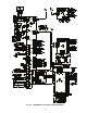
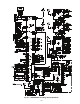
correctly. See Fig. 63-65 for 30XA wiring diagrams.
To use the Service Test mode, the Enable/Off/Remote Con-
tact switch must be in the OFF position. Use the display keys to
move to the Service Test mode. The items are described in the
Service Test table. There are two sub-modes available. Service
Test Enable, T.REQ allows for manual control of the
compressors and minimum load control. In this mode the com-
pressors will operate only on command. The capacity control
and head pressure control algorithms will be active. The con-
denser fans will operate along with the EXVs. There must be a
load on the chiller to operate for an extended period of time.
All circuit safeties will be honored during the test. Quick Test
Enable, Q.REQ allows for test of EXVs, condenser fans,
pumps, low ambient head pressure control speed control, oil