
Operating instructions

36
DUAL CHILLER PUMP CONTROL FOR PARALLEL
CHILLER APPLICATIONS — It is recommended that a
dedicated pump be used for each unit. The chiller must start
and stop its own water pump located on its own piping. If
pumps are not dedicated for each chiller, chiller isolation
valves are required and each chiller must open and close its
own isolation valve.
DUAL CHILLER CONTROL FOR SERIES APPLICA-
TIONS — To configure the master chiller for series applica-
tions using the Touch Pilot™ display, see Table 32. To
configure the master chiller for series applications using the
Navigator™ display, see Table 33.
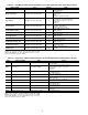
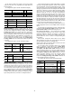
To configure the slave chiller for series applications using
the Touch Pilot™ display, see Table 34. To configure the slave
chiller for series applications using the Navigator™ display,
see Table 35. A power cycle is required for the values to take
effect.
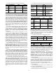
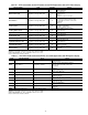
Table 32 — Dual Master Chiller Control Parameters for Series Applications with Touch Pilot™ Display
NOTE: If pump control is configured to OFF, then LAG UNIT PUMP
SELECT = 1. If pump control is set to any other value, then LAG
UNIT PUMP SELECT = 0. This configuration must be set consis-
tently for both master and slave chillers.
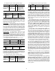
Table 33 — Dual Master Chiller Control Parameters for Series Applications with Navigator™ Display
NOTE: If pump control is configured to OFF, then LAG UNIT PUMP
SELECT = 1. If pump control is set to any other value, then LAG
UNIT PUMP SELECT = 0. This configuration must be set consis-
tently for both master and slave chillers.
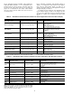
DISPLAY NAME PATH LINE NO. VALUE
Master/Slave Select Main Menu
ConfigMST_SLV 3
1 (Master)
Default: 0 (Disable)
Master Control Type Main Menu
ConfigMST_SLV 7
1 (Local Control)
2 (Remote Control)
3 (CCN Control)
Default: 1 (Local Control)
Value: Configure for proper control type.
Slave Address Main Menu
ConfigMST_SLV 11
Must be set to the Slave Chiller’s address.
The master and slave chiller must have
different addresses and be on the same
Bus Number
Default: 2
Lead Lag Select Main Menu
ConfigMST_SLV 12
0 (Master Always Leads)
1 (Lag Once Failed Only)
2 (Lead/Lag Runtime Select)
Default: 0 (Master Always Leads)
Lead/Lag Balance Delta Main Menu
ConfigMST_SLV 16
Range: 40 to 400 hours
Default: 168 hours
Lag Start Timer Main Menu
ConfigMST_SLV 17
Range: 2 to 30 minutes
Default: 10 minutes
Lead Pulldown Time Main Menu
ConfigMST_SLV 18
Range: 0 to 60 minutes
Default: 0 minutes
Start If Error Higher Main Menu
ConfigMST_SLV 19
Range: 3.0 to 18 F (1.7 to 10.0 C)
Default: 4.0 F (2.2 C)
Lag Minimum Running Time Main Menu
ConfigMST_SLV 20
Range: 0 to 150 minutes
Default: 0 minutes
Lag Unit Pump Control Main Menu
ConfigMST_SLV 21
0 (Stop If Unit Stops)
1 (Run If Unit Stops)
Default: 0 (Stop If Unit Stops)
Chiller In Series Main MenuConfigMST_SLV 22
Ye s
Default: No
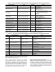
ITEM ITEM EXPANSION PATH VALUE
MSSL Master/Slave Select ConfigurationRSET
Master
Default: Disable
SLVA Slave Address Configuration
RSET
Must be set to the Slave Chiller’s address.
The master and slave chiller must have
different addresses and be on the same
Bus Number
Default: 2
LLBL Master Lead Lag Select Configuration
RSET
Range: Always Lead, Lag if Fail, Runtime Sel
Default: Always Lead
LLBD Lead/Lag Balance Delta Configuration
RSET
Range: 40 to 400 hours
Default: 168 hours
LLDY Lag Start Delay Configuration
RSET
Range: 2 to 30 minutes
Default: 10 minutes
LL.ER Start If Error Higher Configuration
RSET
Range: 3.0 to 18 F (1.7 to 10.0 C)
Default: 4.0 F (2.2 C)
LAG.M Lag Unit Pump Select Configuration
RSET
Range: Off If U Stp, On If U Stop
Default: Off If U Stp
LPUL Lead Pulldown Time Configuration
RSET
Range: 0 to 60 minutes
Default: 0 minutes
SERI Chillers in Series Configuration
RSET
YES
Default: NO
OPER Operating Control Type Operating ModesSLCT Set to desired value