
Operating instructions

59
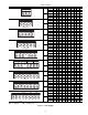
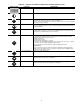
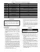
Table 43 — Schnieder Altivar 21 VFD Operating Parameters
PRE-START-UP
Do not attempt to start the chiller until the following checks
have been completed.
System Check
1. Check auxiliary components, such as the chilled fluid
circulating pump, air-handling equipment, or other
equipment to which the chiller supplies liquid are opera-
tional. Consult manufacturer’s instructions. If the unit has
field-installed accessories, be sure all are properly
installed and wired correctly. Refer to unit wiring
diagrams.
2. Open compressor suction service valves (if equipped).
3. Open discharge line, liquid line, oil line, and economizer
(if equipped) service valves.
4. Fill the chiller fluid circuit with clean water (with recom-
mended inhibitor added) or other non-corrosive fluid to be
cooled. Bleed all air out of high points of system. If out-
door temperatures are expected to be below 32 F (0° C),
and unit has a flooded cooler option, sufficient inhibited
propylene glycol or other suitable corrosion inhibited anti-
freeze should be added to the chiller water circuit to pre-
vent possible freeze-up.
The chilled water loop must be cleaned before the unit is
connected. Units supplied with the accessory hydronic
package include a run-in screen. If the run-in screen is left
in the suction guide/strainer, it is recommended that the
Service Maintenance be set to alert the operator within
24 hours of start-up to be sure that the run-in screen in the
suction guide/strainer is removed. To set the time for the
parameter, go to Water Filter Ctrl (days), W.FIL. Val-
ues for this item are counted as days. Refer to the hydron-
ic pump package literature if unit is equipped with the
optional hydronic pump package.
5. Check tightness of all electrical connections.
6. Electrical power source must agree with unit nameplate.
7. Oil separator heaters must be firmly seated under the oil
separator, and must be energized for 24 hours prior to
start-up.
8. Verify power supply phase sequence. Fan motors are 3
phase. Check rotation of non low-ambient controlled fans
by using the quick test. Fan rotation is counterclockwise
as viewed from top of unit. If fan is not turning counter-
clockwise, reverse 2 of the power wires at the main termi-
nal block.
9. Perform service test to verify proper operation.
START-UP
Actual Start-Up —
Actual start-up should be done only
under supervision of a qualified refrigeration technician.
1. Be sure all oil, suction valves, discharge valves (if
equipped) and liquid line service valves are open.
2. Using the unit control, set leaving-fluid set point (Cool-
ing Setpoint 1, CSP.1). No cooling range adjustment is
necessary.
3. If optional control functions or accessories are being
used, the unit must be properly configured. Refer to
Configuration Options section for details.
4. Start the chilled fluid pump, if unit is not configured for
pump control. (Cooler Pumps Sequence, PUMP=0)
5. Complete the Start-Up Checklist to verify all components
are operating properly.
6. If unit is equipped with navitgator turn Enable/Off/Remote
contact switch to Enable position. If unit is equipped with
Touch Pilot press the Start/Stop button and select Local On.
7. Allow unit to operate and confirm that everything is
functioning properly. Check to see that leaving fluid
temperature agrees with leaving set point Control Point
(Control Point, CTPT).
PARAMETER NAME VALUE
uLu Rated Motor Voltage Nominal motor voltage(V) from rating plate
F201 VIA Speed Reference Level 1 5
F202 VIA Output Frequency Level 1 0
F203 VIA Speed Reference Level 2 100
F204 VIA Output Frequency Level 2 60
F401 Slip compensation 60%
F415 Rated Motor Current Nominal motor current(A) from rating plate
F417 Rated Motor Speed Nominal motor speed(RPM) from rating plate
F701 Keypad display: % or A/V 1
tHr Motor Rated Current Overload Setting Nominal motor current(A) from rating plate
uL Rated Motor Frequency 60 Hz
FH Maximum Frequency 60 Hz
LL Low Speed 0 Hz
UL High Speed 60 Hz
ACC Ramp-up Time 10 Sec
dEC Ramp-down Time 10 Sec
cnod Remote Mode Start/Stop Control 0 (Control terminal logic inputs)
fnod
Remote Mode Primary Speed reference
Source
1 (VIA)
IMPORTANT: Complete the Start-Up Checklist
for 30XA Liquid Chillers at the end of this publication.
The checklist assures proper start-up of a unit, and
provides a record of unit condition, application
requirements, system information, and operation at
initial start-up.
CAUTION
Do not manually operate contactors. Serious damage to the
machine may result.