
Operating instructions

71
No additional capacity will be added until the circuit’s su-
perheat is greater than 18° F (10° C). The control will look for
other circuits to add capacity if additional steps of capacity are
required. This mode will terminate once the affected circuit’s
superheat is greater than 18° F (10° C).
If this condition is encountered, see Possible Causes for
Alarms P.11, P.12 and P.13 on page 98.
Sensors — The electronic control uses up to 17 thermistors
to sense temperatures and up to 12 transducers to sense
pressure for controlling chiller operation. These sensors are
outlined below.
THERMISTORS (Tables 46-47B) — Thermistors that are
monitoring the chiller’s operation include: Cooler Entering
Water, Cooler Leaving Water, Dual Chiller Leaving Water,
Compressor Suction Gas Temperature, Compressor Discharge
Gas Temperature, Economizer Temperature, Compressor Motor
Temperature, and Outdoor Air Temperature Thermistors. These
thermistors are 5 kat 77 F (25 C) and are identical in tempera-
ture versus resistance. The Space Temperature Thermistor is
10 k at 77 F (25 C) and has a different temperature vs.
resistance.
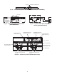
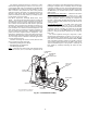
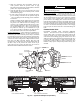
Cooler Leaving Water Sensor
— On all sizes, this thermistor
is installed in a friction fit well in the leaving water nozzle of
the cooler. See Fig. 42 and 43.
Cooler Entering Water Sensor
— On all sizes, this thermistor
is factory-installed in a friction fit well in the entering water
nozzle of the cooler.
Suction Gas Temperature
— On all sizes, this thermistor is
factory-installed in a friction fit well located on the compressor
of each circuit. There is one thermistor for each circuit.
Compressor Discharge Gas Temperature
— On all sizes, this
thermistor is factory-installed in a friction fit well located in the
discharge end of the compressor for the circuit. There is one
thermistor for each circuit.
Economizer Temperature
— On all sizes except 080 and 082,
this thermistor is factory-installed in a friction fit well located
in the economizer line for the circuit. There is one thermistor
for each circuit.
Compressor Motor Temperature
— On all sizes, this therm-
istor is embedded in the motor windings. There are two therm-
istors in each compressor. One spare is provided.
Outdoor Air Temperature
— This sensor is factory-installed
to the back of the control box.
Remote Space Temperature
— This sensor (part no.
33ZCT55SPT) is a field-installed accessory mounted in the in-
door space and is used for water temperature reset. The sensor
should be installed as a wall-mounted thermostat would be (in
the conditioned space where it will not be subjected to either a
cooling or heating source or direct exposure to sunlight, and 4
to 5 ft above the floor).
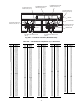
Space temperature sensor wires are to be connected to
terminals in the unit main control box. See Fig. 44. The space
temperature sensor includes a terminal block (SEN) and a RJ11
female connector. The RJ11 connector is used access into
the Carrier Comfort Network
®
(CCN) at the sensor.
To connect the space temperature sensor (see Fig. 44):
1. Using a 20 AWG twisted pair conductor cable rated for
the application, connect one wire of the twisted pair to
one SEN terminal and connect the other wire to the other
SEN terminal located under the cover of the space
temperature sensor.
2. Connect the other ends of the wires to terminals 7 and 8
on TB6 located in the unit control box.
Units on the CCN can be monitored from the space at the
sensor through the RJ11 connector, if desired. To wire the RJ11
connector into the CCN:
1. Cut the CCN wire and strip ends of the red (+), white
(ground), and black (–) conductors. (If another wire color
scheme is used, strip ends of appropriate wires.)
2. Insert and secure the red (+) wire to terminal 5 of the
space temperature sensor terminal block.
3. Insert and secure the white (ground) wire to terminal 4 of
the space temperature sensor.
4. Insert and secure the black (–) wire to terminal 2 of the
space temperature sensor.
5. Connect the other end of the communication bus cable to
the remainder of the CCN communication bus.
NOTE: The Energy Management Module (EMM) is required
for this accessory.
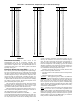
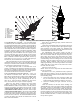
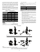
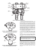
TRANSDUCERS — There are four pressure transducers per
circuit, and two different types of transducers: low pressure
(green connector) and high pressure (black connector).
Low Pressure Type: Suction Pressure Transducer (SPT), Econ-
omizer Pressure Transducer (EPT).
High Pressure Type: Discharge Pressure Transducer (DPT),
Oil Pressure Transducer (OPT). See Fig. 45A and 45B for
transducer locations.
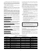
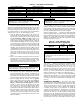
Table 46 — Thermistor Identification
*SGTA and SGTB for 30XA080,082 units are connected to the EXVA board.
IMPORTANT: The cable selected for the RJ11
connector wiring MUST be identical to the CCN
communication bus wire used for the entire network.
Refer to Table 14 for acceptable wiring.
THERMISTOR ID DESCRIPTION RESISTANCE AT 77 F (25 C) CONNECTION POINT
EWT Entering Water Thermistor 5k MBB-J6-CH2
LWT Leaving Water Thermistor 5k MBB-J6-CH1
OAT Outdoor Air Thermistor 5k MBB-J6-CH4
SGTA* Circuit A Suction Gas Thermistor 5k EXVA-J3-THA
SGTB* Circuit B Suction Gas Thermistor 5k EXVB-J3-THA
SGTC Circuit C Suction Gas Thermistor 5k EXVC-J3-THA
DGTA Circuit A Discharge Gas Thermistor 5k CPM-A-J9-CH02
DGTB Circuit B Discharge Gas Thermistor 5k CPM-B-J9-CH02
DGTC Circuit C Discharge Gas Thermistor 5k CPM-C-J9-CH02
ECTA Circuit A Economizer Thermistor 5k EXVA-J3-THB
ECTB Circuit B Economizer Thermistor 5k EXVB-J3-THB
ECTB Circuit C Economizer Thermistor 5k EXVC-J3-THB
DUAL Dual Chiller LWT Thermistor 5k MBB-J6-CH3
CAMT Circuit A Motor Temperature 5k CPM-A-J9-CH01
CBMT Circuit B Motor Temperature 5k CPM-B-J9-CH01
CCMT Circuit C Motor Temperature 5k CPM-C-J9-CH01
SPT Space Temperature Thermistor 10k EMM-J6-CH2