
Operating instructions

79
5. When the compressor starts successfully, observe the
cooler pressure. When the pressure reads 10 psig
(68.9 kPa), turn the Emergency Switch (SW2) to the OFF
position. The compressor should stop.
6. Open the liquid line service valve and allow the unit to
restart normally. If low oil level alarms persist, continue
with the following steps.
7. If none of the previous steps were successful, the unit is
low on oil charge. Add oil to the oil separator using the
1
/
4
in. access fitting that the discharge pressure transducer
is mounted to.
NOTE: To facilitate the oil charging process, ensure that
the unit is not running when adding oil. The system is un-
der pressure even when the unit is not running, so it is
necessary to use a suitable pump to add oil to the system.
Using a suitable pump, add
1
/
2
gal (1.9 l) of oil to the sys-
tem. Continue adding oil in
1
/
2
gal (1.9 l) increments until
the problem is resolved, up to a maximum of 1.5 gal
(5.7 l). If it is necessary to add factory oil charge levels to
the system contact your local Carrier representative.
Oil Filter Maintenance
— Each circuit has one oil filter locat-
ed externally to the compressor. Oil line pressure drop is
monitored by the control. Oil line pressure drop is calculated
by subtracting oil pressure (OP) from discharge pressure (DP).
If the oil line pressure drop exceeds 30 psi (206.8 kPa) for
5 minutes the control will generate a High Oil Filter Pressure
Drop alert. The High Oil Filter Pressure Drop alert will
not shut down the compressor, but instead indicates that the
oil filter is dirty. If oil pressure line losses exceed 50 psi
(344.7 kPa) then the control will shut down the circuit on
Maximum Oil Filter Differential Pressure Failure.
Replacing the Oil Filter
— Close the oil line ball valve locat-
ed in front of the oil filter. Connect a charging hose to the
1
/
4
-in.
access fitting port located downstream of the valve and bleed
off oil trapped between the service valve and the oil solenoid
valve. A quart of oil is typically what is removed during this
process. Remove the charging hose. Unscrew the nuts from
both ends of the oil filter and remove the oil filter. Remove the
protective caps from the new oil filter and install, being careful
not to lose or damage the new O-ring located on the new oil fil-
ter. Draw a vacuum at the Schrader port. Remove the charging
hose and open the oil line ball valve. Check both fittings for
leaks.
Flooded Cooler Units
FLOODED COOLER UNIT SUCTION SERVICE
VALVE — The suction service valve is a factory-installed op-
tion for 30XA units. It is located in the suction outlet of the
cooler. The suction service valve is bolted between the cooler
outlet and the suction flange piping. The suction service valve
shaft has a locking device located on the shaft to lock the valve
in either a fully open position or a fully closed position. The
locking device must be pulled out prior to moving the valve
handle to a fully open or a fully closed position. See Fig. 51A
and 51B.
CAUTION
Compressor oil is pressurized. Use proper safety precau-
tions when relieving pressure.
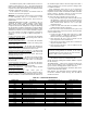
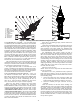
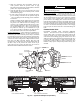
SOLENOID 1
SOLENOID 2
HIGH PRESSURE
SWITCH
MOTOR TEMPERATURE
SENSOR 2
COMMON
MOTOR TEMPERATURE
SENSOR 1
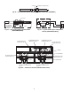
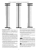
text
Compression
Process
High Pressure Oil
De-energized
FLOW
Valve #2 (NO)
De-energized
NO FLOW
Valve #1 (NC)
Bleed Line to Low Pressure Suction
l
Discharge
Port
Unloader Piston
Chamber
text
Compression
Process
Loaded Position
High Pressure Oil
Energized
NO FLOW
Valve #2 (NO)
Energized
FLOW
Valve #1 (NC)
Bleed Line to Low Pressure Suction
Slide Valve
Disc harge
Port
Unloader Piston
Chamber
Loaded Position
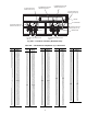
High with
High
Pressure
Oil
Drain to
Low Pressure
Unloaded Position
Slide Valve
text
High Pressure Oil
Trapped
Oil at
High
Pressure
Compression
Process
Part Load Position
Energized
NO FLOW
Valve #2 (NO)
De-energized
NO FLOW
Valve #1 (NC)
Bleed Line to Low Pressure Suction
Slide Valve
Discharge
Port
Unloader Piston
Chamber
Slide Valve
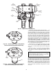
FULLY LOADED OPERATION FULLY UNLOADED OPERATION
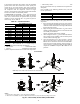
MAINTAIN POSITION
OIL PRESSURE
TRANSDUCER
LOCATION
DISCHARGE
GAS THERMISTOR
ACCESS
FITTING
SUCTION
TEMPERATURE
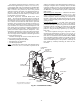
Fig. 49 — Typical 06T Compressor (All Units)
a30-4469