
Operating instructions


90
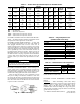
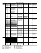
Table 59 — Alarm Codes
LEGEND
PREFIX
CODE
SUFFIX
CODE
ALARM
NUMBER
ALARM DESCRIPTION REASON FOR ALARM
ACTION TAKEN
BY CONTROL
RESET
TYPE
PROBABLE CAUSE
th 01 1 Cooler Entering Fluid
Thermistor
Temperature measured
by the controller is
outside of the range
of –40 F to 245 F
(–40 C to 118 C)
Unit be shut down or
not allowed to start
Automatic Faulty Sensor,
wiring error or failed
main base board
02 2 Cooler Leaving Fluid
Thermistor
03 3 Circuit A Defrost Thermistor Temperature measured
by the controller is
outside of the range
of –40 F to 245 F
(–40 C to 118 C)
None
Automatic
Configuration error
04 4 Circuit B Defrost Thermistor
06 5 Condenser Entering
Fluid Thermistor
07 6 Condenser Leaving
Fluid Thermistor
08 7 Reclaim Condenser
Entering Thermistor
09 8 Reclaim Condenser
Leaving Thermistor
10 9 OAT Thermistor Temperature measured
by the controller is
outside of the range
of –40 F to 245 F
(–40 C to 118 C)
Unit be shut down or
not allowed to start
Automatic
Faulty Sensor,
wiring error or failed
main base board
11 10 Master/Slave Common Fluid
Thermistor
Temperature measured
by the controller is
outside of the range
of –40 F to 245 F
(–40 C to 118 C)
Dual chiller deacti-
vated. Master and
slave machines
operate in stand-
alone mode
12 11 Circuit A Suction Gas
Thermistor
Temperature measured
by the controller is
outside of the range
of –40 F to 245 F
(–40 C to 118 C)
Circuit shut down or
not allowed to start
Automatic
Faulty Sensor,
wiring error, failed
EXV or CPM board
13 12 Circuit B Suction Gas
Thermistor
14 13 Circuit C Suction Gas
Thermistor
15 14 Circuit A Discharge Gas
Thermistor
16 15 Circuit B Discharge Gas
Thermistor
17 16 Circuit C Discharge Gas
Thermistor
18 17 Circuit A Condenser Sub-
cooling Liquid Thermistor
Temperature measured
by the controller is
outside of the range
of –40 F to 245 F
(–40 C to 118 C)
None
Automatic
Configuration error
19 18 Circuit B Condenser Sub-
cooling Liquid Thermistor
21 19 Space Temperature
Thermistor
Temperature measured
by the controller is
outside of the range
of –40 F to 245 F
(–40 C to 118 C)
Alarm tripped
Automatic
Faulty Sensor, wiring
error, failed EMM
board
23 20 Cooler heater feedback
thermistor
Temperature measured
by the controller is
outside of the range
of –40 F to 245 F
(–40 C to 118 C)
None
Automatic
Configuration error
24 21 Circuit A Economizer Gas
Thermistor
Temperature measured
by the controller is
outside of the range
of –40 F to 245 F
(–40 C to 118 C)
Circuit economizer
function disabled
Automatic
Faulty Sensor,
wiring error, failed
EXV board
25 22 Circuit B Economizer Gas
Thermistor
26 23 Circuit C Economizer Gas
Thermistor
Pr 01 24 Circuit A Discharge
Transducer
Measured voltage is
0 vdc or SST > EWT and
EXV < 50% for 1 minute
Circuit shut down or
not allowed to start
Automatic Faulty transducer,
wiring error, failed
main base board or
fan board
02 25 Circuit B Discharge
Transducer
03 26 Circuit C Discharge
Transducer
04 27 Circuit A Suction Transducer
05 28 Circuit B Suction Transducer
06 29 Circuit C Suction Transducer
07 30 Circuit A Reclaim Pump-
down Pressure Transducer
Measured voltage is
0 vdc or SST > EWT and
EXV < 50% for 1 minute
None
Automatic
Configuration error
08 31 Circuit B Reclaim Pump-
down Pressure Transducer
CCN — Carrier Comfort Network® HPS — High Pressure Switch
CPM — Compressor Protection Module LWT — Leaving Water Temperature
DX — Direct Expansion MOP — Maximum Operating Pressure
EMM — Energy Management Module MTA — Must Trip Amps
EWT — Entering Water Temperature OAT — Outdoor Air Temperature
EXV — Electronic Expansion Valve SST — Saturated Suction Temperature
HGBP — Hot Gas Bypass UL — Underwriters Laboratories