AQUASNAP® 30RAP010-150 Air-Cooled Chillers with ComfortLink Controls Controls, Start-Up, Operation, Service, and Troubleshooting CONTENTS Page SAFETY CONSIDERATIONS . . . . . . . . . . . . . . . . . . . . . . . 2,3 GENERAL . . . . . . . . . . . . . . . . . . . . . . . . . . . . . . . . . . . . . . . . . 3-6 Conventions Used in this Manual. . . . . . . . . . . . . . . . . . . .3 Basic Controls Usage . . . . . . . . . . . . . . . . . . . . . . . . . . . . . . .3 CONTROLS. . . . . . . . . . . . . . . . . . .
CONTENTS (cont) WARNING Page • EPM CHIP • LOSS OF CCN COMMUNICATIONS • REPLACING DEFECTIVE MODULES Hydronic Package. . . . . . . . . . . . . . . . . . . . . . . . . . . . . . . . . . 64 MAINTENANCE . . . . . . . . . . . . . . . . . . . . . . . . . . . . . . . . . . . . 65 Recommended Maintenance Schedule. . . . . . . . . . . . . 65 Microchannel Heat Exchanger (MCHX) Condenser Coil Maintenance and Cleaning Recommendations . . . . . . . . . . . . . . . . . . . . . . . . . . . . . . .
value represents a configuration setting, an explanation will be shown in parenthesis after the value. As an example, ConfigurationOPT2LLCS = 1 (Automatic). Pressing the ESCAPE and ENTER keys simultaneously will scroll an expanded text description of the point name or value across the display. The expanded description is shown in the local display tables but will not be shown with the path names in text.
ENTER so that the item value flashes. Use the arrow keys to change the value or state and press the ENTER key to accept it. Press the ESCAPE key to return to the next higher level of structure. Repeat the process as required for other items. When a specific item is located, the item name alternates with the value. Press the ENTER key at a changeable item and the value will be displayed. Press ENTER again and the value will begin to flash indicating that the value can be changed.
Table 3 — Operating Modes MODE NO. ITEM EXPANSION DESCRIPTION 01 CSM CONTROLLING CHILLER Chillervisor System Manager (CSM) is controlling the chiller. 02 WSM CONTROLLING CHILLER Water System Manager (WSM) is controlling the chiller. 03 MASTER/SLAVE CONTROL Ramp load (pull-down) limiting in effect. In this mode, the rate at which leaving fluid temperature is dropped is limited to a predetermined value to prevent compressor overloading. See Cooling Ramp Loading (ConfigurationSLCTCRMP).
ACCESSORY NAVIGATOR™ DISPLAY MODULE — The Navigator module provides a mobile user interface to the ComfortLink control system, which is only available as a fieldinstalled accessory. The display has up and down arrow keys, an ENTER key, and an ESCAPE key. These keys are used to navigate through the different levels of the display structure. Press the ESCAPE key until ‘Select a Menu Item’ is displayed to move through the top 11 mode levels indicated by LEDs on the left side of the display. See Fig. 2.
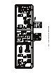
LOCATED OVER EMM AND EXV EMM EXV FB-1 CHC TRAN CCB AUX CSB-A1 UPC LON DISCONNECT OPTION/TB TB1 TB4 MS- MSCWP1 CWP2 FAN 1 C-A1 MBB CWP1 CWP2 MM A1 COMPRESSOR CONTROL BOX a30-4962 Fig. 3 — Typical Control Box for 30RAP010,015 LOCATED OVER EMM AND EXV FB-1 EXV EMM CHC CCB-1 FB-3 TRAN CCB-2 4 AUX LON TB1 CSB-A1 CSB-A2 UPC TB4 FAN 1 FAN 2 C-A1 MBB FC1/MM CWP1 CWP2 COMPRESSOR A1 A2/B1 CONTROL BOX Fig.
TRAN-2 FR-1 CB-1 C-A1 CSB-A1 TRAN-1 FR-2 C-A2 CSB-A2 CB-2 FC-1 MM 8 FC-3 AUX MBB UPC TB4 TB1 LOCATED OVER EMM AND EXV LON EXV CHC B1 B2 CONTROL BOX END A1 A2 COMPRESSORS FAN 2 FAN 1 FR-4 CSB-B2 CB-4 C-B2 055,060 UNIT ONLY CWP1 CWP2 FAN 4 FR-3 MS- MSCWP1 CWP2 FAN 3 C-B1 CSB-B1 CB-3 Fig.
Fig.
a30-5376 Fig.
a30-5377 Fig.
STANDARD TERMINAL BLOCK OPTIONAL DISCONNECT CB1A TB1A PER NEC TO FUSED DISCONNECT PER NEC 2 3 21 11 TO FUSED DISCONNECT 1 CCB-1 22 12 23 13 BLK BLK BLK YEL YEL YEL 11 12 22 BLU 13 23 YEL BLU BLK CCB-2 BLK 11 21 YEL 12 22 BLU 13 23 H2 H3 HF ~ TRAN3 H1 SECONDARY 115V X1 YEL BLU GRN/YEL XF GFI-CO FIOP/ACCESSORY 2 BLK 2 BLK 22 YEL 13 23 BLU 1 T1 2 COMP A1 T2 3 T3 GRN/YEL CH-A2 11 21 BLK 12 22 YEL 13 23 BLU 1 T1 2 COMP A2 T2 3 T3 CHILL
CB1 5 AMPS RED TRAN1 MBB TB4 5 ORN J10A 1 1 RLY 11 3 BRN GRA A1 PNK ORN FC1 18 1 BRN BLK BLK BLK SEE NOTE 7 BRN A2 FC2 M1 VIO SEE NOTE 11 FC2 A2 SEE NOTE 11 7 LVT RED 6 GRA 5 GRA 4 3 HR BRN HEAT/BOILER FIELD INSTALLED WIRING 4 CWFS BLK 2 2 VIO J11 LVT 2 WHT 1 10 4 3 C TB1 A1 CA1 A2 BRN C TB1 BRN A2 CA2 BRN A2 CA1 BRN C TB1 BRN A2 CWP2 BRN A2 CWP1 A1 CA2 A2 1 25 VIO 2 24 RED A1 CWP A2 1 A1 CWP A2 2 J6 2 1 1 J3 2 3 4 9
STANDARD TERMINAL BLOCK OPTIONAL DISCONNECT CB1A CCB-1 TB1A PER NEC TO FUSED DISCONNECT PER NEC 2 3 BLK BLK BLK BLK BLK 21 11 TO FUSED DISCONNECT 1 22 13 23 YEL BLU YEL BLU BLK CCB-2 11 21 YEL 12 22 BLU 13 23 11 21 BLK 12 22 YEL 13 YEL BLK CA1 BLK 21 BLK BLU BLU BLU BLU BLU BLU 23 13 11 12 BLU YEL YEL YEL YEL YEL 22 12 BLK YEL CH-A1 BLU BLK 380V,460V,575V ONLY CSB-A1 YEL BLU 11 21 BLK 12 22 YEL 13 23 BLU EQUIP GND FU6 BLK RED 1 1 H2 H3 H4 HF
CB1 5 AMPS a30-5378 RED TRAN1 MBB J10A 1 1 RLY 11 4 5 9 PNK ORN BLK BLK PL2-1 M1 VIO SEE NOTE 14 PL2-5 VIO SEE NOTE 14 PNK LVT 18 1 23 PL1-1 ORN M1 VIO SEE NOTE 14 GRA M2 VIO GRA VIO VIO LVT VIO J12 TAN RED 1 25 2 24 RED 4 5 4 3 ALMR HR BRN HEAT/BOILER FIELD INSTALLED WIRING LVT 1 4 5 3 J6 2 (055,060 ONLY) TAN 4 CWFS BLK 1 TAN 2 WHT 10 A2 FR3 0 A1 CB2 A2 1 FR4 0 1 J3 2 3 4 9 ORN 11 9 1 2 J4 12 3 4 5 13 6 14 13 REMOTE ON-OFF
a30-5454 Fig.
CB1 8 AMPS RED TRAN1 MBB TB4 5 ORN J10A 1 1 6 ORN HPS-B BLU BLK BLK PL4-1 16 M1 VIO M1 M2 VIO RED BLK PL1-1 M1 VIO SEE NOTE 11 M2 VIO VIO 1 25 2 24 ORN 6 BLU 11 6 4 HR VIO BRN CWFS 2 BLK WHT 2 1 10 9 ORN 8 9 RED 7 SW1 A1 ENABLE RED OFF C1 B1 RED RED 7 5 GRA 14 13 PL51-1 ORN PL51-2 ORN CWP1 14 13 PL51-3 BLU PL51-4 BLU LEN CCN WHT (COM) BLK (-) (+) RED SHIELD J1 BLK 2 WHT 3 RED 4 BRN 5 RED 6 BLK 7 WHT 8 RED ORN ORN BLU BLU 4
OPTIONAL DISCONNECT (SINGLE POINT,380/460/575V ONLY) STANDARD TERMINAL BLOCK CB1A CCB-1 TB1A PER NEC TO FUSED DISCONNECT TO FUSED DISCONNECT PER NEC 2 BLK BLK BLK BLK BLK BLK 21 11 1 22 12 380-3-60 460-3-60 FNQ-R-1.
CB1 8 AMPS RED TRAN1 MBB TB4 5 ORN J10A 1 1 PNK A1 PNK FC1 A1 ORN HPS-B BLK BLK PL4-1 PL4-2 MP-B1 ORN M1 VIO PL5-1 M2 VIO PNK RLY 1 21 RLY 2 23 M1 VIO FC2 A2 RLY 3 25 RLY 4 27 M2 VIO 1 A2 BRN C TB1 PNK A1 CB2 A2 BRN C TB1 LVT J12 5 21 PL49-7 HPS-A BLK RED PL1-1 BLU A1 FC3 A2 BRN C TB1 ORN A1 CA1 A2 BRN C TB1 GRA A1 CA2 A2 BRN C TB1 C TB1 PL1-2 MP-A1 VIO M1 VIO M1 M2 VIO BLK PL2-1 PL2-2 MP-A2 GRA M2 VIO PL51-6 VIO LV
OPTIONAL DISCONNECT STANDARD TERMINAL BLOCK (SINGLE POINT,380V,460V,575V ONLY) CB1A DISCONNECT OPTION ONLY, CONNECT TO TERMINAL BLOCK FOR STANDARD TB1A PER NEC TO FUSED DISCONNECT TO FUSED DISCONNECT PER NEC 2 CCB-1 BLK BLK BLK BLK BLK BLK 21 11 1 22 12 380-3-60 460-3-60 500VA 208/230-3-60 FNQ-R-2 JKS-60 JKS-30 JKS-30 15 BLU CSB-A3 BLK 23 BLK 11 YEL BLU YEL 12 22 BLU 13 23 BLK 11 BLK YEL 12 22 NONE LP-CC-30 BLU 13 23 TB VOLTAGE HZ 1 208/230/460/575 60 13A
CB1 8 AMPS RED TRAN1 MBB a30-5456 J10A TB4 5 ORN 1 1 6 11 12 13 14 15 16 17 18 19 20 RLY 1 21 RLY 2 23 22 24 RLY 3 25 RLY 4 27 26 RLY 1 PNK A1 PNK FC1 ORN HPS-B 1 RED BLU BLK BLK PL4-1 3 11 RLY 6 14 12 13 PNK M1 VIO M1 FC2 A1 BRN A2 FC4 A1 CB1 A2 A2 BRN C TB1 M2 VIO PNK A1 CB2 A2 BRN C TB1 ALM R 18 ALMR VIO HEAT/BOILER FIELD INSTALLED WIRING 2 17 CWPI 3 SEE NOTE 9 HR BR 1 CWFS 2 4 4 BRN 2 10 RED BLU PL49-8 11 BLK BLK BLK WHT
LEGEND FOR FIG.
a30-5381 Fig. 14 — CCN Wiring Diagram Energy Management Module (EMM) — The EMM module is available as a factory-installed option or as a fieldinstalled accessory. The EMM module receives 4 to 20 mA inputs for the leaving fluid temperature reset, cooling set point and demand limit functions. The EMM module also receives the switch inputs for the field-installed 2-stage demand limit and ice done functions.
which should be blinking whenever power is on. Check LEN connections for potential communication errors at the board J3 and/or J4 connectors. Communication between modules is accomplished by a 3-wire sensor bus. These 3 wires run in parallel from module to module. The J4 connector on the MBB provides both power and communication directly to the marquee display only. YELLOW LED — The MBB has one yellow LED. The Carrier Comfort Network (CCN) LED will blink during times of network communication.
Units on the CCN can be monitored from the space at the sensor through the RJ11 connector, if desired. To wire the RJ11 connector into the CCN (Fig. 17): Table 7 — CCN Communication Bus Wiring MANUFACTURER Alpha American Belden Columbia Manhattan Quabik PART NO. Regular Wiring Plenum Wiring 1895 — A21451 A48301 8205 884421 D6451 — M13402 M64430 6130 — IMPORTANT: The cable selected for the RJ11 connector wiring MUST be identical to the CCN communication bus wire used for the entire network.
Energy Management Module (Fig.
LEAD/LAG DETERMINATION — This is a configurable choice and is factory set to be automatic for all units. The 30RAP units offer an optional digital compressor. When the unit is equipped with a digital scroll compressor and enabled (ConfigurationUNITA1.TY=YES), or minimum load, then circuit A is lead (ConfigurationOPT2LLCS).
Table 8 — Part Load Data Percent Displacement, Standard Units with Minimum Load Valve 30RAP UNIT SIZE 010 015 018 020 025 030 035 040 045 050 055 060 070 080 090 100 115 130 150 CONTROL STEPS 1 1 1 2 3 1 2 3 1 2 3 1 2 3 1 2 3 4 5 1 2 3 4 5 1 2 3 4 5 1 2 3 4 5 1 2 3 4 5 1 2 3 4 5 1 2 3 4 5 6 1 2 3 4 5 6 7 1 2 3 4 5 6 7 1 2 3 4 5 6 1 2 3 4 5 6 7 1 2 3 4 5 6 7 1 2 3 4 5 6 7 CAPACITY STEPS % Displacement 100 100 100 50 *20 100 50 *24 100 50 *29 100 50 *32 100 77 50 23 *9 100 73 50 23 *11 100 7
2 STARTS DEADBAND EXAMPLE 47 7 6 46 45 LWT (F) LWT (C) 8 44 43 42 5 41 0 200 400 600 800 1000 3 STARTS TIME (SECONDS) STANDARD DEADBAND LEGEND LWT — Leaving Water Temperature MODIFIED DEADBAND Minimum Load Control — If equipped, the minimum load control valve is energized only when one compressor is running on Circuit A and capcity is decreasing, provided that the minimum run time for Circuit B compressors has been satisfied.
a30-5459 OFM1 OFM3 OFM2 TOP VIEW SIZES 035-050 130-150 ONLY OFM2 TOP VIEW SIZES 018-030 CONTROL BOX CONTROL BOX TOP VIEW SIZES 010,015 100-150 ONLY CONTROL BOX OFM1 CONTROL BOX CONTROL BOX OFM1 OFM1 OFM3 OFM2 OFM4 OFM1 OFM3 OFM5 OFM7 OFM9 OFM2 OFM4 OFM6 OFM8 OFM10 TOP VIEW SIZES 070-150 080-150 ONLY NOT ON 100,130 TOP VIEW SIZES 055,060 Fig. 21 — 30RAP Condenser Fan Layout The schedule number can be set anywhere from 65 to 99 for operation under a CCN global schedule.
Table 9 — Fan Stages 30RAP UNIT SIZE 010,015 018-030 035-050 055,060 070 080-090 100 115 130 150 FAN STAGES Contactor Energized FC1 FC1 FC1,2 FC1 FC2 FC1,2 FC3 FC1,3 FC3,2 FC1,2,3 FC1 FC3 FC4 FC3 FC2 FC4 FC1 FC1,4 FC3,4 FC1,3 FC1,3,4 FC4 FC2 FC2,4 FC3,4 FC2,3 FC2,3,4 FC5 FC1,5 FC1,5,6 FC2 FC2,4 FC2,3 FC2,3,4 FC5 FC5,1 FC5,6 FC5,1,6 FC2 FC2,4 FC2,3 FC2,3,4 FC7 FC7,5 FC7,6 FC7,6,5 FC2 FC2,4 FC2,4,1 FC2,1,3 FC2,1,3,4 FC1 FC1,7 FC1,6 FC1,6,8 FC1,6,8,7 FC1,6,8,7,5 FC1 FC1,2 FC1,3 FC1,3,8 FC1,3,8,2 FC1,3,
possible. This results in operation at increased saturated condensing temperature. As a result, some models may not be able to achieve rated efficiency. For chiller operation at rated efficiency, disable the low sound mode or adjust the low sound mode start and stop times accordingly or set both times to 00:00 for rated efficiency operation 24 hours per day.
As stated before, there are certain alarm conditions and Operating Modes that will turn the cooler pump relay ON. This sequence will describe the normal operation of the pump control algorithm. When the unit cycles from an “On” state to an “Off” state, the cooler pump output will remain energized for the Cooler Pump Shutdown Delay (ConfigurationOPT1PM.DY). This is configurable from 0 to 10 minutes. The factory default is 1 minute.
Selection, any pump that has an active alert will not be allowed to start. With the dual integral pump package, the Cooler Pump Starter will be energized when the machine is in an occupied period. As part of the factory-installed package, an auxiliary set of contacts is wired to the MBB to serve as Chilled Water Pump Interlock, one set for each pump to individual channels on the MBB. With a call for mechanical cooling, the specific pump interlock and flow switch are checked.
limit Pump Changeover Hours (ConfigurationOPT1 PM.DT) is reached, the lead pump will be turned OFF. Ap- Refer to Table 11 for dual chiller configuration. In this example the master chiller will be configured at address 1 and the slave chiller at address 2. The master and slave chillers must reside on the same CCN bus (ConfigurationCCN CCNB) but cannot have the same CCN address (ConfigurationCCNCCNA).
Table 11 — Dual Chiller Configuration (Master Chiller Example) SUB-MODE ITEM KEYPAD ENTRY DISPLAY ITEM EXPANSION COMMENTS ENTER CTRL CONTROL METHOD ENTER 0 SWITCH DEFAULT 0 ESCAPE OPT2 CCN ADDRESS DEFAULT 1 CCN BUS NUMBER DEFAULT 0 DISP UNIT OPT1 OPT2 CTRL CCN CCNA ENTER 1 CCNB CCN CCNB ENTER 0 ESCAPE CCN PROCEED TO SUBMODE RESET RSET 36
Table 11 — Dual Chiller Configuration (Master Chiller Example) (cont) SUB-MODE ITEM LLEN LLEN MSSL KEYPAD ENTRY DISPLAY ITEM EXPANSION ENTER CRST COOLING RESET TYPE LLEN LEAD/LAG CHILLER ENABLE SLVA DSBL SCROLLING STOPS ENTER DSBL VALUE FLASHES ENBL SELECT ENBL ENTER ENBL ESCAPE LLEN LEAD/LAG CHILLER ENABLE MSSL MASTER /SLAVE SELECT ENTER MAST MASTER /SLAVE SELECT ESCAPE MSSL LLBD 0 SCROLLING STOPS ENTER 0 VALUE FLASHES 2 SELECT 2 ENTER 2 ESCAPE SLVA SLAVE ADDRES
Table 12 — Dual Chiller Configuration (Slave Chiller Example) SUB-MODE ITEM KEYPAD ENTRY DISPLAY ITEM EXPANSION COMMENTS ENTER CTRL CONTROL METHOD 0 SWITCH DEFAULT 0 (SEE NOTE 1) CCN ADDRESS SCROLLING STOPS DISP UNIT OPT1 OPT2 CTRL ESCAPE OPT2 CCN CCNA CCNA ENTER 1 ENTER 1 VALUE FLASHES 2 SELECT 2 (SEE NOTE 2) CCN CCNA CCNB ENTER 2 ESCAPE CCN ENTER 0 ESCAPE CCN CCN ADDRESS CHANGE ACCEPTED CCN BUS NUMBER DEFAULT 0 (SEE NOTE 3) PROCEED TO SUBMODE RSET RSET ENTER LLEN
Table 13 — 4 to 20 mA Reset SUB-MODE DISPLAY ITEM EXPANSION CRST 1 COOLING RESET TYPE MA.DG 5.0 F (2.8 C) DEGREES COOL RESET KEYPAD ENTRY ITEM ENTER RSET COMMENT 0 = no reset 1 = 4 to 20 mA input 2 = Outdoor air temp 3 = Return Fluid 4 = Space Temperature Default: 0° F (0° C) Reset at 20 mA Range: –30 to 30 F (–16.7 to 16.7 C) NOTE: The example above shows how to configure the chiller for 4 to 20 mA reset. No reset will occur at 4.0 mA input, and a 5.0 F reset will occur at 20.0 mA.
Table 15 — Configuring Outdoor Air and Space Temperature Reset MODE (RED LED) KEYPAD ENTRY SUBMODE ENTER DISP KEYPAD ENTRY DISPLAY ITEM EXPANSION COMMENT 4 COOLING RESET TYPE 2 = Outdoor-Air Temperature 4 = Space Temperature (Connect to LVT-22,23) 85 °F 72 °F REMOTE - NO RESET TEMP Default: 125.0 F (51.7 C) Range: 0° to125 F (–17.8 to 51.7 C) RM.F 55 °F 68 °F REMOTE - FULL RESET TEMP Default: 0.0° F (–17.8 C) Range: 0° to 125 F (–17.8 to 51.7 C) RM.
Under normal operation, the chiller will maintain a constant leaving fluid temperature approximately equal to the chilled fluid set point. As the cooler load varies, the entering cooler fluid will change in proportion to the load as shown in Fig. 27. Usually the chiller size and leaving-fluid temperature set point are selected based on a full-load condition. At part load, the fluid temperature set point may be colder than required.
DEMAND LIMIT (CCN Loadshed Controlled) — To configure Demand Limit for CCN Loadshed control set the Demand Limit Select (ConfigurationRSETDMDC) to 3. Then configure the Loadshed Group Number (ConfigurationRSETSHNM), Loadshed Demand Delta (ConfigurationRSETSHDL), and Maximum Loadshed Time (ConfigurationRSETSHTM). See Table 17. The Loadshed Group number is established by the CCN system designer. The ComfortLink controls will respond to a Redline command from the Loadshed control.
Digital Scroll Option — The 30RAP010-090 units have a factory-installed option for a digital scroll compressor which provides additional stages of unloading for the unit. The digital compressor is always installed in the A1 compressor location. When a digital compressor is installed, a digital unloader solenoid (DUS) is used on the digital compressor.
CSP.1) or (Set PointsCOOLCSP.2), or if reset is used, with the control point (Run StatusVIEW CTPT). 6. Check the cooler leaving chilled water temperature to see that it remains well above 32 F (0° C), or the brine freezing point if the unit is a medium temperature brine unit. 7. Recheck compressor oil level (see Oil Charge section).
Example: Supply voltage is 240-3-60. AB = 243 v BC = 236 v AC = 238 v Table 20 — Minimum Fluid Volume in Circulation 30RAP UNIT SIZE 010,015 018-030 035-150 NORMAL AIR PROCESS COOLING OR CONDITIONING LOW AMBIENT OPERATION APPLICATION APPLICATION gal/ton (L per kW) gal/ton (L per kW) Std Unit HGBP Digital Std Unit HGBP Digital 12 (13) N/A 3 (3.3) 12 (13) N/A 6 (6.5) 6 (6.5) 4 (4.3) 3 (3.3) 10 (10.8) 10 (10.8) 6 (6.5) 3 (3.3) 3 (3.3) 3 (3.3) 6 (6.5) 6 (6.5) 6 (6.5) 1.
controls the position of the electronic expansion valve stepper motor to maintain superheat set point. The MBB controls the superheat leaving cooler to approximately 9° F (5° C). Because EXV status is communicated to the main base board (MBB) and is controlled by the EXV boards, it is possible to track the valve position. The unit is then protected against loss of charge and a faulty valve. Just prior to compressor start, the EXV will open. At low ambient temperatures the EXV is closed at start up.
1. 2. 3. 4. 5. 6. 7. 8. 9. 10. Cable Glass Seal Motor Housing Stepper Motor Bearing Lead Screw Insert Valve Piston Valve Seat Valve Port Fig. 30 — Cutaway View of the Electronic Expansion Valve (Size 070-150 Shown) FIELD SERVICING INSTRUCTIONS — The EXV valves on sizes 025, 030, and 050-150 can be serviced. See Fig. 30 for a cutaway view of the EXV for sizes 070-150. Motor kits for the EXV valve on sizes 025, 030, and 050-150 are available as replacement parts.
from the motor prior to installation. For 025, 030, 050060 sizes, replacement motors are shipped in the retracted position and may be installed as received; therefore, this step may be skipped if installing a new motor. BLK WHT CAUTION GRN RED If the existing motor has been removed for inspection or cleaning, be sure that the piston is fully retracted into the motor assembly before installation on the valve. Failure to do so will permanently damage the drive and motor.
INCLUDED IN CABLE KIT CABLE CABLE CABLE RETAINER MOTOR AND ADAPTER ASSEMBLY MOTOR ADAPTER ASSEMBLY CABLE RETAINER GASKET MOTOR ADAPTER ASSEMBLY SIGHTGLASS SPORLAN FLOW DIRECTION a30-4971 NORMAL FLOW DIRECTION Fig. 32 — Electronic Expansion Valve Details (010-060) DISASSEMBLY CLOSED ADAPTER 27mm / 11/16'' OPEN NOTE: Open valve in OPEN QuickVALVE Test sub-mode before disassembling.
(sizes 010-030) or to the bottom bracket (sizes 035-150) using the hardware removed in Step 4. Reconnect the cooler heater if required. For sizes 010-025, torque the bolts to 7-10 ft-lb. For sizes 030-150, torque the bolts to 30-50 ft-lb. 6. Carefully braze the refrigerant lines to the connections on the heat exchanger. Lines should be soldered using silver as the soldering material with a minimum of 45% silver.
the coil face. Reduce pressure and use caution to prevent damage to air centers. UNIT SIZES 100-150 MANUFACTURER OIL ICI. . . . . . . . . . . . . . . . . . . . . . . . . . . . Emkarate RL 32H Do not reuse drained oil or any oil that has been exposed to the atmosphere. CAUTION Excessive water pressure will fracture the braze between air centers and refrigerant tubes. Microchannel Heat Exchanger (MCHX) Condenser Coil Maintenance and Cleaning Recommendations Check Refrigerant Feed Components (Fig.
DPT HPS SPT RGT SUCTION RGT SPT ACCESS VALVE DISCHARGE ACCESS VALVE EWT a30-4974 DTT A1 A2 B1 B2 OIL SIGHT GLASS DPT DTT EWT HPS LWT RGT SPT LWT DISCHARGE ACCESS VALVE DPT FLOW SWITCH HPS — — — — — — — LEGEND Discharge Pressure Thermostat Discharge Temperature Thermistor Entering Water Thermistor High Pressure Switch Leaving Water Thermistor Return Gas Thermistor Suction Pressure Transducer Fig.
installed, are designed to protect the cooler and/or hydronic package from freezing down to –20 F (–29 C). Power for these heaters is supplied from the main unit power. The input from the low pressure transducer provides a backup cooler freeze protection package. The MBB shuts down the unit when a low pressure condition exists that could cause the cooler to freeze up.
value read by the control in the Temperatures mode using the scrolling marquee display. 1 Pressure Transducers — The suction and discharge 2 transducers are different part numbers and can be distinguished by the color of the transducer body, suction (yellow) and discharge (red). No pressure transducer calibration is required. The transducers operate on a 5 vdc supply, which is generated by the main base board (MBB). See Fig. 38 for transducer connections to the J8 connector on the MBB.
Table 25 — 5K Thermistor Temperatures (°F) vs. Resistance/Voltage Drop (Voltage Drop for EWT, LWT, RGT, and OAT) TEMP (F) –25 –24 –23 –22 –21 –20 –19 –18 –17 –16 –15 –14 –13 –12 –11 –10 –9 –8 –7 –6 –5 –4 –3 –2 –1 0 1 2 3 4 5 6 7 8 9 10 11 12 13 14 15 16 17 18 19 20 21 22 23 24 25 26 27 28 29 30 31 32 33 34 35 36 37 38 39 40 41 42 43 44 45 46 47 48 49 50 51 52 53 54 55 56 57 58 VOLTAGE DROP (V) 3.699 3.689 3.679 3.668 3.658 3.647 3.636 3.624 3.613 3.601 3.588 3.576 3.563 3.550 3.536 3.523 3.509 3.494 3.
Table 26 — 5K Thermistor Temperatures (°C) vs. Resistance/Voltage Drop (Voltage Drop for EWT, LWT, RGT, and OAT) TEMP (C) –32 –31 –30 –29 –28 –27 –26 –25 –24 –23 –22 –21 –20 –19 –18 –17 –16 –15 –14 –13 –12 –11 –10 –9 –8 –7 –6 –5 –4 –3 –2 –1 0 1 2 3 4 5 6 7 8 9 10 11 12 13 14 VOLTAGE DROP (V) 3.705 3.687 3.668 3.649 3.629 3.608 3.586 3.563 3.539 3.514 3.489 3.462 3.434 3.406 3.376 3.345 3.313 3.281 3.247 3.212 3.177 3.140 3.103 3.065 3.025 2.985 2.945 2.903 2.860 2.817 2.774 2.730 2.685 2.639 2.593 2.547 2.
Table 27 — 10K Thermistor Temperature (°F) vs. Resistance/Voltage Drop (For SPT) TEMP (F) –25 –24 –23 –22 –21 –20 –19 –18 –17 –16 –15 –14 –13 –12 –11 –10 –9 –8 –7 –6 –5 –4 –3 –2 –1 0 1 2 3 4 5 6 7 8 9 10 11 12 13 14 15 16 17 18 19 20 21 22 23 24 25 26 27 28 29 30 31 32 33 34 35 36 37 38 39 40 41 42 43 44 45 46 47 48 49 50 51 52 53 54 55 56 57 58 59 60 VOLTAGE DROP (V) 4.758 4.750 4.741 4.733 4.724 4.715 4.705 4.696 4.686 4.676 4.665 4.655 4.644 4.633 4.621 4.609 4.597 4.585 4.572 4.560 4.546 4.533 4.519 4.
Table 28 — 10K Thermistor Temperature (°C) vs. Resistance/Voltage Drop (For SPT) TEMP (C) –32 –31 –30 –29 –28 –27 –26 –25 –24 –23 –22 –21 –20 –19 –18 –17 –16 –15 –14 –13 –12 –11 –10 –9 –8 –7 –6 –5 –4 –3 –2 –1 0 1 2 3 4 5 6 7 8 9 10 11 12 13 14 VOLTAGE DROP (V) 4.762 4.748 4.733 4.716 4.700 4.682 4.663 4.644 4.624 4.602 4.580 4.557 4.533 4.508 4.482 4.455 4.426 4.397 4.367 4.335 4.303 4.269 4.235 4.199 4.162 4.124 4.085 4.044 4.003 3.961 3.917 3.873 3.828 3.781 3.734 3.686 3.637 3.587 3.537 3.485 3.433 3.
step in the motor shaft. For proper performance, fan should be positioned such that it is securely seated on this step. Apply removeable threadlocker Loctite 242 to threads. Tighten the bolt to 15 ± 1 ft-lb (20 ± 1.3 N·m). The flow sensor cable is provided with (3) LEDs that indicate if 24 vac power is present and also status of the switch contacts.
VFD. It should not be removed with power applied to the VFD. LOSS OF CCN COMMUNICATIONS — Carrier Comfort Network® (CCN) communications with external control systems can be affected by high frequency electrical noise generated by the Motormaster V control. Ensure unit is well grounded to eliminate ground currents along communication lines.
LOW AMBIENT OPERATION (MOTORMASTER V) FIOP/ACCESSORY MM-A FB1 FB3 1 BLK 11 21 BLK 11 21 BLK L1 T1 BLK-1 YEL 12 22 YEL 12 22 YEL L2 T2 BLK-2 BLU 13 BLU 23 13 L3 BLU 23 T3 VIO 11 *1 25 240 1/4W 2 FB2 BLK 11 21 BLK 11 YEL 12 22 YEL 12 BLU 13 23 BLU 13 22 BLK-2 BLK-3 BLK WHT LEGEND Auxiliary Fuse Block Motormaster Outdoor Fan Motor Terminal Block 8 6 BLK VOLTAGE HZ 1 208/230/460/575 60 13A 380 60 1 2 OFM2 3 1 GRN/YEL 3 2 BLK BLK COOLER/PUM
Table 30 — Fault Codes FAULT CODE AF CF cF CL DESCRIPTION High Temperature Fault: Ambient temperature is too high; Cooling fan has failed (if equipped). Control Fault: A blank EPM, or an EPM with corrupted data has been installed. Incompatibility Fault: An EPM with an incompatible parameter version has been installed. CURRENT LIMIT: The output current has exceeded the CURRENT LIMIT setting (Parameter 25) and the drive is reducing the output frequency to reduce the output current.
Table 31 — Motormaster® V Program Parameters for Operating Modes PARAMETERS P01 P02 P03 P04 P05 P06 P08 P09 P10 P11 P12 P13 P14 P15 P16 P17 P19 P20 P21 P22 P23 P24 P25 P26 P27 P28 P29 P30 P31 P32 P33 P34 P35 P36 P37 P38 P39 P40 P41 P42 P43 P44 P45 P46 P47 P48 P61 P62 P63 P64 P65 P66 P67 P68 P69 DESCRIPTION Line Voltage: 01 = low line, 02 = high line Carrier Freq: 01 = 4 kHz, 02 = 6 kHz, 03 = 8 kHz Startup mode: flying restart Stop mode: coast to stop Standard Speed source: 01= keypad, 04=4-20mA (NO PI), 05
PUMP PERFORMANCE CHECK — The factory-installed pumps in the 30RAP units are shipped with a single impeller size available for that pump. The pump was selected based on the flow and head requirements as provided to Carrier. It is not uncommon for actual pump duty to be different than what was anticipated at time of selection. In many cases, it may be desirable to make some field modifications to obtain optimum pump performance.
the coil face. Reduce pressure and use caution to prevent damage to air centers. MAINTENANCE Recommended Maintenance Schedule — The following are only recommended guidelines. Jobsite conditions may dictate that maintenance schedule is performed more often than recommended. Routine: • Periodic clean water rinse, especially in coastal and industrial applications. • Check condenser coils for debris, clean as necessary.
runs unloaded, the longer it must cool before the bi-metal disk resets. See Fig. 44 for approximate reset times. To manually reset ASTP, the compressor should be stopped and allowed to cool. If the compressor is not stopped, the motor will run until the motor protector trips, which occurs up to 90 minutes later. Advanced scroll temperature protection will reset automatically before the motor protector resets, which may take up to 2 hours.
2. Check the thermistor protection chain located in the compressor as follows: a. De-energize control circuit and module power. b. Remove the sensor leads from the module (S1 and S2). Measure the resistance of the thermistor protection chain through these sensor leads with an ohmmeter. NOTE: Turning off power to the module will reset it immediately. CAUTION Restoring the compressor sooner may cause a destructive temperature build up in the scrolls.
password, 1111. Press ENTER for each character. If the password has been changed, use the arrow keys to change each individual character. Toggle the display to “YES” and press ENTER . The alarms will be reset. until the sub-menu item RCRN “RESET ENTER and ALL CURRENT ALARMS” is displayed. Press ENTER . The control will prompt the user for a password, by displaying PASS and WORD.
Table 34 — Alarm and Alert Codes ALARM/ ALERT CODE ALARM OR ALERT DESCRIPTION WHY WAS THIS ALARM GENERATED? ACTION TAKEN BY CONTROL RESET METHOD PROBABLE CAUSE Alert Circuit A, Compressor 1 Failure Compressor feedback signal does not match relay state Compressor A1 shut down. Manual High-pressure switch open, faulty CSB, loss of condenser air, filter drier plugged, noncondensables, operation beyond capability.
Table 34 — Alarm and Alert Codes (cont) ALARM/ ALERT CODE ALARM OR ALERT DESCRIPTION WHY WAS THIS ALARM GENERATED? ACTION TAKEN BY CONTROL RESET METHOD Automatic Thermistor failure, damaged cable/wire or wiring error. PROBABLE CAUSE T073 Alert Outside Air Thermistor Failure Thermistor outside range of –40 to 245 F (–40 to 118 C) Temperature reset disabled. Chiller runs under normal control/set points. When capacity reaches 0, cooler/pump heaters are energized.
Table 34 — Alarm and Alert Codes (cont) ALARM/ ALERT CODE ALARM OR ALERT DESCRIPTION WHY WAS THIS ALARM GENERATED? ACTION TAKEN BY CONTROL RESET METHOD PROBABLE CAUSE Circuit shut down Automatic, only after first 3 daily occurrences. Manual reset thereafter. Reading from OAT sensor must drop 5 F (2.8 C) before restart Faulty transducer/ restricted condenser airflow, low refrigerant charge, faulty EXV. Circuit shut down Automatic restart after first daily occurrence. Manual restart thereafter.
Table 34 — Alarm and Alert Codes (cont) ALARM/ ALERT CODE ALARM OR ALERT DESCRIPTION WHY WAS THIS ALARM GENERATED? ACTION TAKEN BY CONTROL RESET METHOD T190 Alert Cooler Pump 1 Aux Contacts Failed to Close at Start-Up Pump 1 Auxiliary Contacts did not close within 26 seconds after pump was started Pump 1 turned off. Pump 2 will be started if available.
Table 34 — Alarm and Alert Codes (cont) ALARM/ ALERT CODE ALARM OR ALERT T206 Alert DESCRIPTION High Leaving Chilled Water Temperature WHY WAS THIS ALARM GENERATED? ACTION TAKEN BY CONTROL LWT is greater than control point and LCW Alert Limit, and capacity is at 100% for one minute. Alert only. No action taken. RESET METHOD PROBABLE CAUSE Automatic Building load greater than unit capacity, or compressor fault. Check for other alarms/alerts. Both EWT and LWT must be at least 6 F (3.
In addition, if a compressor stuck failure occurs and the current sensor board reports the compressor and the request off, certain diagnostics will take place as follows: 1. If any of the compressors are diagnosed as stuck on and the current sensor board is on and the request is off, the control will command the condenser fans to maintain normal head pressure. 2. The control will shut off all other compressors. The possible causes include welded contactor or frozen compressor relay on the MBB.
8 seconds, or the suction pressure is below 23 psig (158.6 kPa). The cause of this alert may be low refrigerant charge, plugged liquid line filter drier, or sticking EXV. Check head pressure operation. If not equipped, consider adding low ambient temperature head pressure control. Add wind baffles if required. A140 (Reverse Rotation Detected) — A test is made once, when compressor is energized, for suction pressure change on the first activated circuit. The unit control determines failure as follows: 1.
Cooler Flow/Interlock Contacts Opened During Normal Operation Alarm. When this alarm occurs, the chiller will be shut down. The pre-alert (P201) will be reset automatically; the alarm (A201) will require manual reset. Possible Causes: If this condition is encountered, check the following items: • chilled water flow switch, for proper operation. • flow switch cable, for power and control. • check the chilled water loop to be sure that it is completely filled with water, and all air has been purged.
APPENDIX A — DISPLAY TABLES Run Status Mode and Sub-Mode Directory SUB-MODE ITEM EWT LWT SETP CTPT LOD.F DISPLAY ITEM DESCRIPTION AUTO VIEW OF RUN STATUS xxx.x °F Entering Fluid Temp xxx.x °F Leaving Fluid Temp xxx.x °F Active Set Point xxx.x °F Control Point xxx Load/Unload Factor STAT Control Mode VIEW LD.PM OCC LS.AC MODE CAP STGE ALRM TIME YES/NO YES/NO YES/NO xxx x xxx xx.
APPENDIX A — DISPLAY TABLES (cont) Run Status Mode and Sub-Mode Directory (cont) SUB-MODE PM VERS ITEM PUMP SI.PM P.1.DN P.2.DN P.1.MN P.2.MN PMDT P.1.M0 P.1.M1 P.1.M2 P.1.M3 P.1.M4 P.2.M0 P.2.M1 P.2.M2 P.2.M3 P.2.M4 STRN SI.ST S.T.DN S.T.MN ST.DT S.T.M0 S.T.M1 S.T.M2 S.T.M3 S.T.M4 COIL SI.CL C.L.DN C.L.MN CL.DT C.L.M0 C.L.M1 C.L.M2 C.L.M3 C.L.
APPENDIX A — DISPLAY TABLES (cont) Service Test Mode and Sub-Mode Directory SUB-MODE ITEM DISPLAY ITEM DESCRIPTION TEST Service Test Mode EXV.A EXV.B xxx% xxx% OUTPUTS EXV% Open EXV% Open FAN1 ON/OFF Fan 1 Relay FAN2 ON/OFF Fan 2 Relay FAN3 ON/OFF Fan 3 Relay FAN4 FAN5 ON/OFF ON/OFF Fan 4 Relay Fan 5 Relay FAN6 ON/OFF Fan 6 Relay FAN7 FAN8 V.HPA V.HPB CLP.1 CLP.2 DIG.P CL.HT CCH.A CCH.B RMT.A ON/OFF ON/OFF xx xx ON/OFF ON/OFF xxx ON/OFF ON/OFF ON/OFF ON/OFF CC.A1 DIG.P CC.A2 CC.
APPENDIX A — DISPLAY TABLES (cont) Pressures Mode and Sub-Mode Directory SUB-MODE ITEM PRC.A DP.A SP.A PRC.B DP.B SP.B DISPLAY ITEM DESCRIPTION PRESSURES CIRCUIT A xxx.x PSIG Discharge Pressure xxx.x PSIG Suction Pressure PRESSURES CIRCUIT B xxx.x PSIG Discharge Pressure xxx.x PSIG Suction Pressure COMMENT See Note See Note Set Points Mode and Sub-Mode Directory SUB-MODE COOL HEAD FRZ ITEM DISPLAY CSP.1 CSP.2 CSP.3 xxx.x °F xxx.x °F xxx.x °F H.DP F.ON F.OFF B.OFF F.DLT xxx.x °F xxx.
APPENDIX A — DISPLAY TABLES (cont) Outputs Mode and Sub-Mode Directory SUB-MODE GEN.O A.EXV B.EXV CIR.A CIR.B ITEM FAN1 FAN2 FAN3 FAN4 FAN5 FAN6 FAN7 FAN8 V.HPA V.HPB C.WP1 C.WP2 CLHT MLV.R EXV.A APPR AP.SP X.SH.R S.SH.R SH_R OVR.A SPH.A ASH.S AMP.S PLM.A SPR.1 EXV.B APPR AP.SP OVR.B SPH.B ASH.S AMP.S PLM.B SPR.2 CC.A1 DPE.R CC.A2 CC.A3 CC.B1 CC.B2 CC.
APPENDIX A — DISPLAY TABLES (cont) Configuration Mode and Sub-Mode Directory SUB-MODE DISP UNIT OPT1 ITEM DISPLAY ITEM DESCRIPTION DISPLAY CONFIGURATION Test Display LEDs Metric Display TEST METR ON/OFF ON/OFF LANG X PAS.E PASS ENBL/DSBL XXXX SIZE SZA.1 SZA.2 SZA.3 SZB.1 SZB.2 SZB.3 SH.SP FAN.S EXV A1.TY XX XX XX XX XX XX XX X YES/NO YES/NO MAX.T XX FLUD X MLV.S CSB.E CPC PM1E PM2E PM.P.S PM.
APPENDIX A — DISPLAY TABLES (cont) Configuration Mode and Sub-Mode Directory (cont) SUB-MODE OPT2 ITEM DISPLAY ITEM DESCRIPTION UNIT OPTIONS 2 CONTROLS CTRL X Control Method LOAD X Loading Sequence Select LLCS X Lead/Lag Circuit Select LCWT XX High LCW Alert Limit DELY XX Minutes Off Time ICE.M LS.MD ENBL/DSBL X Ice Mode Enable Low Sound Mode Select LS.ST LS.ND 00:00 00:00 Low Sound Start Time Low Sound End Time LS.
APPENDIX A — DISPLAY TABLES (cont) Configuration Mode and Sub-Mode Directory (cont) SUB-MODE ITEM DISPLAY ITEM DESCRIPTION COMMENT CIR A EXV CONFIGURATION EXV.L XX% EXV Opening at Low LWT Default:25% Range:0 to 50% LWT.L XX° F LWT for EXV Min Opening Default:10 F Range:-20 to 40 F EXV.H XX% EXV Opening at High LWT Default:50% Range:0 to 70% LWT.H XX° F LWT for EXV Max Opening Default:35 F Range:20 to 70 F MIN.A XXX EXV CIRC.A Min Position Default: 2 Range: 0 - 100 RNG.
APPENDIX A — DISPLAY TABLES (cont) Configuration Mode and Sub-Mode Directory (cont) SUB-MODE MM ITEM DISPLAY ITEM DESCRIPTION MOTORMASTER Motormaster Select MMR.S YES/NO P.GAN XX Head Pressure P Gain I.GAN XX.X Head Pressure I Gain D.GAN XX.X Head Pressure D Gain MIN.S XX Minimum Fan Speed COMMENT Default: No Default: 1 Range: 1 to 4 Default: 0.1 Range: -20 to 20 Default: 0.0 Range: -20 to 20 Default: 5.
APPENDIX A — DISPLAY TABLES (cont) Configuration Mode and Sub-Mode Directory (cont) SUB-MODE SLCT SERV BCST ITEM DISPLAY ITEM DESCRIPTION SETPOINT AND RAMP LOAD CLSP X Cooling Set Point Select RL.S ENBL/DSBL Ramp Load Select CRMP ENBL/DSBL Cooling Ramp Loading SCHD XX Schedule Number Z.GN X.X Deadband Multiplier EN.A1 EN.A2 EN.A3 EN.B1 EN.B2 EN.B3 REV.R T.D.BC OAT.B G.S.BC BC.
APPENDIX A — DISPLAY TABLES (cont) Time Clock Mode and Sub-Mode Directory SUB-MODE TIME DATE ITEM HH.MM XX Month of Year DOM XX Day of Month DAY X Day of Week STR.M STR.W STR.D MIN.A STP.M STP.W STP.D MIN.S HOL.L HD.01 HD.02 HD.03 HD.04 HD.05 HD.06 HD.07 HD.08 ITEM DESCRIPTION TIME OF DAY XX.
APPENDIX A — DISPLAY TABLES (cont) Time Clock Mode and Sub-Mode Directory (cont) SUB-MODE HD.09 HD.10 HD.11 HD.12 HD.13 HD.14 HD.15 HD.16 HD.17 HD.18 HD.
APPENDIX A — DISPLAY TABLES (cont) Time Clock Mode and Sub-Mode Directory (cont) SUB-MODE HD.20 HD.21 HD.22 HD.23 HD.24 HD.25 HD.26 HD.27 HD.28 HD.29 HD.
APPENDIX A — DISPLAY TABLES (cont) Time Clock Mode and Sub-Mode Directory (cont) SUB-MODE SCH.N SCH.L PER.1 PER.2 PER.3 PER.4 PER.5 ITEM OCC.1 UNC.1 MON.1 TUE.1 WED.1 THU.1 FRI.1 SAT.1 SUN.1 HOL.1 OCC.2 UNC.2 MON.2 TUE.2 WED.2 THU.2 FRI.2 SAT.2 SUN.2 HOL.2 OCC.3 UNC.3 MON.3 TUE.3 WED.3 THU.3 FRI.3 SAT.3 SUN.3 HOL.3 OCC.4 UNC.4 MON.4 TUE.4 WED.4 THU.4 FRI.4 SAT.4 SUN.4 HOL.4 OCC.5 UNC.5 MON.5 TUE.5 WED.5 THU.5 FRI.5 SAT.5 SUN.5 HOL.
APPENDIX A — DISPLAY TABLES (cont) Time Clock Mode and Sub-Mode Directory (cont) SUB-MODE PER.6 PER.7 PER.8 OVR ITEM OCC.6 UNC.6 MON.6 TUE.6 WED.6 THU.6 FRI.6 SAT.6 SUN.6 HOL.6 OCC.7 UNC.7 MON.7 TUE.7 WED.7 THU.7 FRI.7 SAT.7 SUN.7 HOL.7 OCC.8 UNC.8 MON.8 TUE.8 WED.8 THU.8 FRI.8 SAT.8 SUN.8 HOL.8 OVR.T OVR.L T.
APPENDIX A — DISPLAY TABLES (cont) Operating Mode and Sub-Mode Directory SUB-MODE MODE ITEM DISPLAY MD01 MD02 MD03 MD05 MD06 MD07 MD08 MD09 MD10 MD13 MD14 MD15 MD16 MD17 MD18 MD19 MD20 MD21 MD22 MD23 MD24 MD25 MDAO MDBO ON/OFF ON/OFF ON/OFF ON/OFF ON/OFF ON/OFF ON/OFF ON/OFF ON/OFF ON/OFF ON/OFF ON/OFF ON/OFF ON/OFF ON/OFF ON/OFF ON/OFF ON/OFF ON/OFF ON/OFF ON/OFF ON/OFF ON/OFF ON/OFF ITEM DESCRIPTION MODES CONTROLLING UNIT CSM Controlling Chiller WSM Controlling Chiller Master/Slave Control Ramp Load
APPENDIX B — CCN TABLES CCN DISPLAY TABLES — A_UNIT (General Unit Parameters) DESCRIPTION Control Mode Occupied CCN Chiller Low Sound Active Alarm State Active Demand Limit Override Modes in Effect Percent Total Capacity Requested Stage Active Set Point Control Point Entering Fluid Temp Leaving Fluid Temp Emergency Stop Minutes Left for Start PUMPS Cooler Pump Relay 1 Cooler Pump Relay 2 Cooler Pump 1 Interlock Cooler Pump 2 Interlock Cooler Flow Switch Lead Pump Rotate Cooler Pumps Now Heat/Cool Select V
APPENDIX B — CCN TABLES (cont) CCN DISPLAY TABLES — CIRCADIO (Circuit A Discrete Inputs/Outputs) DESCRIPTION CIRC. A DISCRETE OUTPUTS Compressor A1 Relay Compressor A2 Relay Compressor A3 Relay Minimum Load Valve Relay VALUE UNITS POINT NAME FORCIBLE On/Off On/Off On/Off On/Off K_A1_RLY K_A2_RLY K_A3_RLY MLV_RLY N N N N CIRC.
APPENDIX B — CCN TABLES (cont) CCN DISPLAY TABLES — OPTIONS (Unit Parameters) DESCRIPTION FANS Fan 1 Relay Fan 2 Relay Fan 3 Relay Fan 4 Relay Fan 5 Relay Fan 6 Relay Fan 7 Relay Fan 8 Relay Cooler/Pump Heater Off/On Off/On Off/On Off/On Off/On Off/On Off/On Off/On Off/On UNIT ANALOG VALUES Cooler Entering Fluid Cooler Leaving Fluid Lead/Lag Leaving Fluid snnn.n snnn.n snnn.
APPENDIX B — CCN TABLES (cont) CCN CONFIGURATION TABLES — OPTIONS1 (Options 1 Configuration) DESCRIPTION Cooler Fluid Minimum Load Vlv Select CSB Board Enable Cooler Pump Control Cooler Pump 1 Enable Cooler Pump 2 Enable Cooler Pmp Periodic Strt Cooler Pump Select Cooler Pump Shutdown Dly Pump Changeover Hours EMM Module Installed Cnd HX Typ: 0=RTPF 1=MCHX EXV MOP Set Point Config Approach Setpoint VALUE 1 = Water 2 = Med.
APPENDIX B — CCN TABLES (cont) CCN CONFIGURATION TABLES — RESETCON (Temperature Reset and Demand Limit) DESCRIPTION COOLING RESET Cooling Reset Type VALUE DEFAULT UNITS POINT NAME 0 = No Reset 1 = 4-20 mA input 2 = External temp – OAT 3 = Return Fluid 4 = External temp - SPT 0 4-20 MA RESET 4-20 – Degrees Reset –30 to 30 0.0 F 420_DEG REMOTE RESET Remote – No Reset Temp Remote – Full Reset Temp Remote – Degrees Reset 0 to 125 0 to 125 –30 to 30 125.0 0.0 0.
APPENDIX B — CCN TABLES (cont) CCN CONFIGURATION TABLES — DISPLAY (Marquee Display SETUP) DESCRIPTION Service Password Password Enable Metric Display Language Selection VALUE nnnn Enable/Disable Off/On 0 = ENGLISH 1 = FRANCAIS 2 = ESPANOL 3 = PORTUGUES DEFAULT 1111 Enable Off 0 UNITS POINT NAME PASSWORD PASS_EBL DISPUNIT LANGUAGE CCN CONFIGURATION TABLES — EXVACONF (EXV Circuit A Configuration) DESCRIPTION EXV Opening at Low LWT LWT for EXV Min Opening EXV Opening at High LWT LWT for EXV Max Opening EX
APPENDIX B — CCN TABLES (cont) CCN SERVICE TABLES — SERVICE DESCRIPTION SERVICE Brine Freeze Point Pump Service Interval COMPRESSOR ENABLE Enable Compressor A1 Enable Compressor A2 Enable Compressor A3 Enable Compressor B1 Enable Compressor B2 Enable Compressor B3 Reverse Rotation Enable VALUE DEFAULT nnn.n nnnnn UNITS F hours 34.0 876.
APPENDIX B — CCN TABLES (cont) CCN MAINTENANCE TABLES — STRTHOUR DESCRIPTION Machine Operating Hours Machine Starts VALUE nnnnnn nnnnnn UNITS hours POINT NAME HR_MACH CY_MACH Circuit A Run Hours Compressor A1 Run Hours Compressor A2 Run Hours Compressor A3 Run Hours Circuit B Run Hours Compressor B1 Run Hours Compressor B2 Run Hours Compressor B3 Run Hours nnnnnn nnnnnn nnnnnn nnnnnn nnnnnn nnnnnn nnnnnn nnnnnn hours hours hours hours hours hours hours hours HR_CIRA HR_A1 HR_A2 HR_A3 HR_CIRB HR_B1 HR
APPENDIX B — CCN TABLES (cont) CCN MAINTENANCE TABLES — ALARMS DESCRIPTION Active Alarm #1 Active Alarm #2 Active Alarm #3 Active Alarm #4 Active Alarm #5 Active Alarm #6 Active Alarm #7 Active Alarm #8 Active Alarm #9 Active Alarm #10 Active Alarm #11 Active Alarm #12 Active Alarm #13 Active Alarm #14 Active Alarm #15 Active Alarm #16 Active Alarm #17 Active Alarm #18 Active Alarm #19 Active Alarm #20 Active Alarm #21 Active Alarm #22 Active Alarm #23 Active Alarm #24 Active Alarm #25 VALUE Axxx or Txxx A
APPENDIX B — CCN TABLES (cont) CCN MAINTENANCE TABLES — PM-PUMP DESCRIPTION Pump Service Interval Pump 1 Service Countdown Pump 1 Maintenance Done Pump 2 Service Countdown Pump 2 Maintenance Done Pump 1 Maintenance Date Pump 1 Maintenance Date Pump 1 Maintenance Date Pump 1 Maintenance Date Pump 1 Maintenance Date Pump 2 Maintenance Date Pump 2 Maintenance Date Pump 2 Maintenance Date Pump 2 Maintenance Date Pump 2 Maintenance Date VALUE nnnnnn nnnnnn Yes/No nnnnnn Yes/No mm/dd/yy hh:mm mm/dd/yy hh:mm mm/d
APPENDIX B — CCN TABLES (cont) CCN MAINTENANCE TABLES — TESTMODE DESCRIPTION Service Test Mode Compressor A1 Relay Compressor A2 Relay Compressor A3 Relay Compressor A4 Relay Compressor B1 Relay Compressor B2 Relay Compressor B3 Relay Compressor B4 Relay Fan 1 Relay Fan 2 Relay Fan 3 Relay Fan 4 Relay Fan 5 Relay Fan 6 Relay Fan 7 Relay Fan 8 Relay Cooler Pump Relay 1 Cooler Pump Relay 2 Comp A1 Unload Time Minimum Load Valve Relay Remote Alarm Relay EXV % Open EXV % Open VALUE On/Off On/Off On/Off On/Off
APPENDIX B — CCN TABLES (cont) CCN MAINTENANCE TABLES — RUNTEST (cont) DESCRIPTION Minimum Load Valve Relay VALUE On/Off Compressor B1 Feedback Compressor B2 Feedback Compressor B3 Feedback Fan 1 Relay Fan 2 Relay Fan 3 Relay Fan 4 Relay Fan 5 Relay Fan 6 Relay Fan 7 Relay Fan 8 Relay On/Off On/Off On/Off On/Off On/Off On/Off On/Off On/Off On/Off On/Off On/Off Outside Air Temperature Space Temperature Cooler Pump Relay 1 Cooler Pump Relay 2 Cooler Pump 1 Interlock Cooler Pump 2 Interlock Cooler Entering
APPENDIX B — CCN TABLES (cont) CCN MAINTENANCE TABLES — DUALCHIL DESCRIPTION Dual Chiller Link Good? Master Chiller Role VALUE Yes/No Stand Alone, Lead Chiller, Lag Chiller Stand Alone, Lead Chiller, Lag Chiller snnn.n snnn.n snnn.n UNITS F F F LEAD_CP LAG_CP CTRL_PNT Cool EnteringFluid-Slave Cool Leaving Fluid-Slave Cooler Entering Fluid Cooler Leaving Fluid Lead/Lag Leaving Fluid snnn.n snnn.n snnn.n snnn.n snnn.n F F F F F COOLEWTS COOLLWTS COOL_EWT COOL_LWT DUAL_LWT Percent Avail.
APPENDIX C — FACTORY SETTINGS FOR PUMP AND MANUAL STARTERS 30RAP UNIT SIZE 010-060 PUMP SIZE PUMP OPTION* 1.5 HP 2, 9 3 HP 3, 4, B, C 5 HP 5, 6, D, F 7.5 HP 7, G 10 HP Z, H 1, C 3 HP 6, J 2,D (070-130) 5 HP 2,D (150-ton only) 7,K 070-150 3,F (070-130) 7.5 HP 3,F (150-ton only) 8,L 10 HP 4,9,G,M 15 HP 5,B,H,N *Identtified by 12th digit in unit model number.
APPENDIX D — BACNET COMMUNICATION OPTION 6 5 7 8 2 34 5 6 10's 1 9 0 2 34 7 8 9 0 1 The following section is used to configure the UPC Open controller which is used when the BACnet* communication option is selected. The UPC Open controller is mounted in the main control box per unit components arrangement diagrams. TO ADDRESS THE UPC OPEN CONTROLLER — The user must give the UPC Open controller an address that is unique on the BACnet network.
APPENDIX D — BACNET COMMUNICATION OPTION (cont) CONFIGURING THE BAS PORT FOR BACNET MS/ TP — Use the same baud rate and communication settings for all controllers on the network segment. The UPC Open controller is fixed at 8 data bits, No Parity, and 1 Stop bit for this protocol's communications. If the UPC Open controller has been wired for power, pull the screw terminal connector from the controller's power terminals labeled Gnd and HOT.
APPENDIX D — BACNET COMMUNICATION OPTION (cont) Fig. E — BT485 Terminator Installation temperature rating specifications list two acceptable alternatives. The Halar specification has a higher temperature rating and a tougher outer jacket than the SmokeGard specification, and it is appropriate for use in applications where the user is concerned about abrasion. The Halar jacket is also less likely to crack in extremely low temperatures.
APPENDIX D — BACNET COMMUNICATION OPTION (cont) Table D — Open System Wiring Specifications and Recommended Vendors WIRING SPECIFICATIONS Wire Type RECOMMENDED VENDORS AND PART NUMBERS Connect Air Contractors Belden RMCORP Wire and Cable International Description 22 AWG, single twisted shielded pair, low capacitance, CL2P, TC foam FEP, plenum rated. See MS/TP Installation Guide for specifications.
APPENDIX D — BACNET COMMUNICATION OPTION (cont) If the UPC Open is used with the chiller application of Lead/Lag/Standby, all chillers and UPC Open's CCN element numbers must be changed to a unique number in order to follow CCN specifications. In this application, there can only be a maximum of 3 UPC Open controllers on a CCN bus. For the CCN Alarm Acknowledger configuration, the UPC Open defaults to CCN Acknowledger.
APPENDIX D — BACNET COMMUNICATION OPTION (cont) Table G — Network Points List POINT DESCRIPTION 4-20 ma Demand Signal 4-20 ma Reset Signal Active Demand Limit Active Setpoint Alarm State CCN POINT NAME LMT_MA RST_MA DEM_LIM SP READ/ UNITS WRITE R mA R °F R/W % R °F ALM R CCN Chiller CCN Loadshed Signal Circuit A Run Hours Circuit A Starts Circuit B Run Hours CHIL_S_S DL_STAT HR_CIRA CY_CIRA HR_CIRB R/W R R R R Cnd HX TYP:0=RTPF 1=MCHX COILTYP R CY_CIRB CL_MAINT SI_COIL CL_CDOWN A1UNLTME TMP_RGTA
APPENDIX D — BACNET COMMUNICATION OPTION (cont) Table G — Network Points List (cont) POINT DESCRIPTION Control Mode Control Point Cooler Entering Fluid Cooler Fluid Cooler Flow Switch Cooler Freeze Protection Cooler Leaving Fluid Cooler LWT Setpoint Cooler Pump 1 Interlock Cooler Pump 2 Interlock Cooler Pump Relay 1 Cooler Pump Relay 2 Cooler Pump Select Cooler Pump Shutdown Dly Cooler/Pump Heater Cooler Reset Type Cooling Ramp Loading Cooling Setpoint 1 Cooling Setpoint 2 CSM Controlling Chiller Demand
APPENDIX D — BACNET COMMUNICATION OPTION (cont) Table G — Network Points List (cont) POINT DESCRIPTION POINT NAME READ/ UNITS WRITE R R R R R R R R R °F R R R R R R/W °F DEFAULT VALUE RANGE 32.
APPENDIX D — BACNET COMMUNICATION OPTION (cont) Table G — Network Points List (cont) POINT DESCRIPTION Saturated Condensing Tmp Saturated Condensing Tmp Saturated Suction Temp Saturated Suction Temp Slow Change Override Space Temperature Storing ICE Strainer Maint.
APPENDIX E — MAINTENANCE SUMMARY AND LOG SHEETS 30RAP Weekly Maintenance Log Plant ___________________________ Machine Model No. ________________ DATE OIL LEVEL CHECK ALARMS / FAULTS OPERATOR INITIALS REMARKS NOTE: Equipment failures caused by lack of adherence to the Maintenance Interval Requirements are not covered under warranty.
APPENDIX E — MAINTENANCE SUMMARY AND LOG SHEETS (cont) 30RAP Monthly Maintenance Log Month Date Operator UNIT SECTION Compressor Cooler Condenser Controls Starter 117 System 1 / ACTION Check Oil Level Leak Test Inspect and Clean Cooler Inspect Cooler Heater Leak Test Record Water Pressure Differential (PSI) Inspect Water Pumps Leak Test UNIT yes/no yes/no yes/no amps yes/no PSI yes/no yes/no Inspect and Clean Condenser Coil yes/no General Cleaning and Tightening Connections Check Pressure Transd
APPENDIX E — MAINTENANCE SUMMARY AND LOG SHEETS (cont) 30RAP Seasonal Shutdown Log Month Date Operator UNIT SECTION Cooler Controls 1 / 2 / / 3 / ACTION Isolate and Drain Cooler Add Glycol for Freeze Protection Do Not Disconnect Control Power NOTE: Equipment failures caused by lack of adherence to the Maintenance Interval Requirements are not covered under warranty.
INDEX Actual start-up 43 Alarms and alerts 67 Compressor failure alerts 74 Compessor stuck on failure alarms 74 AUX board (AUX) 23 BACnet communications option 107-115 Basic controls usage 3 Brine operation, charge adjustment for 44 Board addresses 23 Brazed-plate cooler heat exchanger Cleaning 50 Replacement 50 Capacity control 26 Capacity control overrides 27 Carrier Comfort Network® (CCN) interface 24 CCN tables 93-105 Chilled fluid proof-of-flow switch open 65 Chilled water flow switch 54 Circuit brea
Copyright 2012 Carrier Corporation Manufacturer reserves the right to discontinue, or change at any time, specifications or designs without notice and without incurring obligations. Catalog No. 04-53300097-01 Printed in U.S.A.
START-UP CHECKLIST FOR 30RAP LIQUID CHILLER (Remove and use for Job File) I.
YES NO 7. INTEGRATED 40 MESH Y STRAINER CLEAN. YES NO 8. WATER LOOP VOLUME GREATER THAN MINIMUM REQUIREMENTS. (See Table 20). YES NO 9. PROPER LOOP FREEZE PROTECTION PROVIDED TO _____ °F (°C). YES ANTIFREEZE TYPE _____________________ CONCENTRATION __________%. IF OUTDOOR AMBIENT IS BELOW 32 F (0° C) THEN ITEMS 9-11 HAVE TO BE COMPLETED TO PROVIDE COOLER FREEZE PROTECTION TO –20 F (–29 C). (REFER TO WINTER SHUTDOWN FOR PROPER COOLER WINTERIZATION PROCEDURE.
YES NO YES NO 1. COMPLETE COMPONENT TEST. YES NO 2. CHECK REFRIGERANT AND OIL CHARGE. YES NO 3. RECORD COMPRESSOR MOTOR CURRENT. YES NO 4. RECORD CONFIGURATION SETTINGS. YES NO 5. RECORD OPERATING TEMPERATURES AND PRESSURES. YES NO 10. VERIFY COOLER FLOW RATE. PRESSURE ENTERING COOLER PRESSURE LEAVING COOLER COOLER PRESSURE DROP Psig X 2.31 ft./psi = kPa X 0.
COMPRESSOR MOTOR CURRENT L1 L2 L3 L1 L2 L3 L1 L2 L3 COMPRESSOR A1 COMPRESSOR A2 COMPRESSOR A3 COMPRESSOR B1 COMPRESSOR B2 COMPRESSOR B3 CONDENSER FAN MOTOR CURRENT FAN MOTOR 1 FAN MOTOR 2 FAN MOTOR 3 FAN MOTOR 4 FAN MOTOR 5 FAN MOTOR 6 FAN MOTOR 7 FAN MOTOR 8 FAN MOTOR 9 FAN MOTOR 10 COOLER PUMP MOTOR CURRENT COOLER PUMP 1 COOLER PUMP 2 Record Software Versions MODE — RUN STATUS SUB-MODE VERS ITEM MBB EXV AUX1 EMM MARQ NAVI CXB DISPLAY ITEM EXPANSION CESR-131460- _ _-_ _ CESR-131172- _ _-_ _
III. Unit Start-Up (cont) RECORD CONFIGURATION SETTINGS UNIT (Configuration Settings) SUBMODE ITEM ITEM EXPANSION DISPLAY ENTRY UNIT CONFIGURATION UNIT SIZE UNIT SIZE XXX SZA.1 COMPRESSOR A1 SIZE XX SZA.2 COMPRESSOR A2 SIZE XX SZA.3 COMPRESSOR A3 SIZE XX SZB.1 COMPRESSOR B1 SIZE XX SZB.2 COMPRESSOR B2 SIZE XX SZB.3 COMPRESSOR B3 SIZE XX SH.SP SUPERHEAT SETPOINT XX.X F FAN.S FAN STAGING SELECT X EXV EXV MODULE INSTALLED YES/NO A1.TY COMPRESSOR A1 DIGITAL? YES/NO MAX.
PRESS ESCAPE KEY TO DISPLAY ‘OPT1’. PRESS DOWN ARROW KEY TO DISPLAY ‘OPT2’. PRESS ENTER KEY. RECORD CONFIGURATION INFORMATION BELOW. OPTIONS2 (Options Configuration) SUBMODE ITEM ITEM EXPANSION DISPLAY ENTRY UNIT OPTIONS 2 CONTROLS OPT2 CTRL CONTROL METHOD X LOAD LOADING SEQUENCE SELECT X LLCS LEAD/LAG CIRCUIT SELECT X LCWT HIGH LCW ALERT LIMIT XX.X F DELY MINUTES OFF TIME XX ICE.M ICE MODE ENABLE ENBL/DSBL LS.MD LOW SOUND MODE SELECT X LS.ST LOW SOUND START TIME 00:00 LS.
III. Unit Start-Up (cont) PRESS ESCAPE KEY TO DISPLAY ‘HP.B’. PRESS DOWN ARROW KEY TO DISPLAY ‘EXV.A’. PRESS ENTER KEY. RECORD CONFIGURATION INFORMATION BELOW. EXV.A (Circuit A EXV Configuration) SUB-MODE EXV.A EXV.L ITEM ITEM EXPANSION EXV OPENING AT LOW LWT DISPLAY XX% XX° F LWT.L LWT FOR EXV MIN OPENING EXV.H EXV OPENING AT HIGH LWT XX% LWT.H LWT FOR EXV MAX OPENING XX° F MIN.A EXV CIRC.A MIN POSITION XXX RNG.A EXVA STEPS IN RANGE XXXXX SPD.A EXVA STEPS PER SECOND XXXXX POF.
PRESS ESCAPE KEY TO DISPLAY ‘EXV.B’. PRESS DOWN ARROW KEY TO DISPLAY ‘MM’. PRESS ENTER KEY. RECORD CONFIGURATION INFORMATION BELOW. MM (Motormaster Configuration Settings) SUB-MODE ITEM MM ITEM EXPANSION DISPLAY MMR.S MOTORMASTER SELECT YES/NO P.GAN HEAD PRESSURE P GAIN XX I.GAN HEAD PRESSURE I GAIN XX.X D.GAN HEAD PRESSURE D GAIN XX.X MIN.S MINIMUM FAN SPEED XX ENTRY PRESS ESCAPE KEY TO DISPLAY ‘MM’. PRESS DOWN ARROW KEY TO DISPLAY ‘RSET’. PRESS ENTER KEY.
III. Unit Start-Up (cont) PRESS ESCAPE KEY TO DISPLAY ‘RSET’. PRESS DOWN ARROW KEY TO DISPLAY ‘SLCT’. PRESS ENTER KEY. RECORD CONFIGURATION INFORMATION BELOW: SLCT (Setpoint and Ramp Load Configuration) SUBMODE ITEM ITEM EXPANSION DISPLAY ENTRY SETPOINT AND RAMP LOAD SLCT CLSP COOLING SETPOINT SELECT X RL.S RAMP LOAD SELECT ENBL/DSBL CRMP COOLING RAMP LOADING X.X SCHD SCHEDULE NUMBER XX Z.GN DEADBAND MULTIPLIER X.
COMPONENT TEST USE ESCAPE/ARROW KEYS TO ILLUMINATE CONFIGURATION LED. PRESS ENTER TO DISPLAY ‘DISP’. PRESS ENTER AGAIN TO DISPLAY ‘TEST’ FOLLOWED BY ‘OFF’. PRESS ENTER TO STOP DISPLAY AT ‘OFF’ AND ENTER AGAIN SO ‘OFF’ DISPLAY FLASHES. ‘PASS’ AND ‘WORD’ WILL FLASH IF PASSWORD NEEDS TO BE ENTERED. PRESS ENTER TO DISPLAY PASSWORD FIELD AND USE THE ENTER KEY FOR EACH OF THE FOUR PASSWORD DIGITS. USE ARROW KEYS IF PASSWORD IS OTHER THAN STANDARD.
Service Test Mode and Sub-Mode Directory (cont) SUB-MODE KEYPAD ENTRY ITEM DISPLAY ENTER CC.A1 ON/OFF COMPRESSOR A1 RELAY DIG.P 0 to 15 COMP A1 UNLOAD PERCENT CC.A2 ON/OFF COMPRESSOR A2 RELAY CC.A3 ON/OFF COMPRESSOR A3 RELAY MLV ON/OFF MINIMUM LOAD VALVE RELAY CC.B1 ON/OFF COMPRESSOR B1 RELAY See Note CC.B2 ON/OFF COMPRESSOR B2 RELAY See Note CC.
_________________________________________________________________________________________ _________________________________________________________________________________________ _________________________________________________________________________________________ _________________________________________________________________________________________ _________________________________________________________________________________________ ______________________________________________________________