
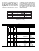
Specifications


43
Digital Scroll Option — The 30RAP010-090 units
have a factory-installed option for a digital scroll compressor
which provides additional stages of unloading for the unit. The
digital compressor is always installed in the A1 compressor lo-
cation. When a digital compressor is installed, a digital unload-
er solenoid (DUS) is used on the digital compressor.
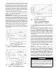
DIGITAL SCROLL OPERATION — A digital scroll oper-
ates in two stages — the "loaded state" when the solenoid valve
is deenergized and the "unloaded state" when the solenoid
valve is energized. During the loaded state, the compressor op-
erates like a standard scroll and delivers full capacity and mass
flow.
However, during the unloaded state, there is no capacity
and no mass flow through the compressor. The capacity of the
system is varied by varying the time the compressor operates
in an unloaded and loaded state during a 15-second period. If
the DUS is energized for 7 seconds, the compressor will be
operating at 47% capacity. If the DUS is energized for 10 sec-
onds, the compressor will be operating at approximately 33%
of its capacity. Capacity is the time averaged summation of
loaded and unloaded states, and its range is continuous from
the minimum configured capacity to 100%. Regardless of
capacity, the compressor always rotates with constant speed.
As the compressor transitions from a loaded to unloaded state,
the discharge and suction pressures will fluctuate and the com-
pressor sound will change.
The ComfortLink controller controls and integrates the op-
eration of the DUS into the compressor staging routine to
maintain temperature control. When a digital compressor is in-
stalled, an additional discharge gas temperature thermistor
(DTT) is installed along with the AUX board for control of the
DUS.
DIGITAL COMPRESSOR CONFIGURATION — When a
digital compressor is installed, the configuration parameter
(Configuration
UNIT
A1.TY) is configured to YES.
There is also a maximum unload time configuration, (Config-
uration
UNIT
MAX.T) that is set to 7 seconds, which in-
dicates the maximum unloading for the digital compressor is
47%. This is done to optimize efficiency of the system.
PRE-START-UP
Do not attempt to start the chiller until following checks
have been completed.
System Check
1. Check all auxiliary components, such as chilled fluid
pumps, air-handling equipment, or other equipment to
which the chiller supplies liquid. Consult manufacturer's
instructions. Verify that any pump interlock contacts have
been properly installed. If the unit has field-installed ac-
cessories, be sure all are properly installed and wired cor-
rectly. Refer to unit wiring diagrams.
2. Use the scrolling marquee display to adjust the Cooling
Set Point.
3. Fill chilled fluid circuit with clean water (with recom-
mended inhibitor added) or other non-corrosive fluid to
be cooled. Bleed all air out of the high points of the sys-
tem. If chilled water is to be maintained at a temperature
below 40 F (4.4 C) or outdoor temperatures are expected
to be below 32 F (0° C), an antifreeze of sufficient con-
centration must be used to prevent freeze-up at anticipat-
ed suction temperatures.
The chilled water loop must be cleaned before the unit is
connected.
NOTE: On units with digital scroll option do not check
refrigerant, charge if compressor is operating at less than
100% capacity, digital operation can be disabled by con-
figuring A1.TY = NO (Configuration
Unit
A1.TY)
4. Check tightness of all electrical connections.
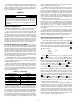
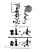
5. Oil should be visible in the compressor sight glass(es).
See Fig. 29. For unit sizes 010-090, an acceptable oil lev-
el is from
1
/
8
to
3
/
8
of sight glass. For unit sizes 100-150,
an acceptable oil level is from
3
/
4
to
7
/
8
of sight glass. No
oil should be removed unless the crankcase heater, if
equipped, has been energized for at least 24 hours. Ad-
just the oil level as required. See Oil Charge section on
page 50 for Carrier approved oils.
6. Electrical power source must agree with unit nameplate.
7. All condenser fan and factory-installed hydronic package
pump motors are three phase. Check for proper rotation
of condenser fans first BEFORE attempting to start
pumps or compressors. To reverse rotation, interchange
any two of the main incoming power leads.
8. Be sure system is fully charged with refrigerant (see
Check Refrigerant Charge section on page 44).
9. Verify proper operation of cooler and hydronic package
heaters (if installed). Heaters operate at the same voltage
as the main incoming power supply and are single phase.
Heater current is approximately 0.4 amps for 460 and
575 v units. Heater current is approximately 0.8 amps for
230 v units.
START-UP AND OPERATION
NOTE: Refer to Start-Up Checklist on pages CL-1 to CL-12.
Actual Start-Up — Actual start-up should be done only
under supervision of a qualified refrigeration mechanic.
1. Be sure all service valves are open.
2. Using the scrolling marquee display, set leaving-fluid set
point (Set Points
COOL
CSP.1). No cooling range
adjustment is necessary.
3. Start chilled fluid pump (if not configured for cooler
pump control).
4. Turn ENABLE/OFF/REMOTE CONTACT switch to
ENABLE position.
5. Allow unit to operate and confirm that everything is func-
tioning properly. Check to see that leaving fluid tempera-
ture agrees with leaving set point (Set Points
COOL
IMPORTANT: Before beginning Pre-Start-Up or Start-Up,
complete Start-Up Checklist for 30RAP Liquid Chiller at
end of this publication (pages CL-1 to CL-12). The check-
list assures proper start-up of a unit, and provides a record
of unit condition, application requirements, system infor-
mation, and operation at initial start-up.
OIL
SIGHT GLASS
Fig. 29 — Sight Glass Location
a30-5515