
Specifications


67
NOTE: Turning off power to the module will reset it immedi-
ately.
For this reason, module power must never be switched with
the control circuit voltage.
Copeland replacement compressors are shipped with two
solid-stage motor protection modules. A 120/240-volt module
is installed and a 24-volt module is shipped with the compres-
sor. The 30RAP units require the 24-volt module be field in-
stalled. Failure to install the 24-volt module will result in a
compressor failure alarm.
See Field Troubleshooting Solid-State Motor Protection
Module below. It may take as long as two hours for the motor
to cool down before the overload will reset. Current sensing
boards monitor to the compressor current. The ComfortLink
control system takes advantage of the compressor overload op-
eration, by locking out the compressor if current draw is not de-
tected. This will prevent unnecessary compressor cycling on a
fault condition until corrective action can be taken.
FIELD TROUBLESHOOTING SOLID-STATE MOTOR
PROTECTION MODULE — Follow the steps listed below
to trouble shoot the module in the field. See wiring diagram in
Fig. 6A-12B or in terminal box cover.
1. De-energize control circuit and module power. Remove
the control circuit wires from the module (Terminals M1
& M2). Connect a jumper across these “control circuit”
wires. This will bypass the “control contact” of the
module.
Re-energize the control circuit and module power. If the
compressor will not operate with the jumper installed,
then the problem is external to the solid state protection
system.
If the compressor operates with the module bypassed but
will not operate when the module is reconnected, then the
control circuit relay in the module is open. The thermistor
protection chain now needs to be tested to determine if
the module's control circuit relay is open due to excessive
internal temperatures or a faulty component.
2. Check the thermistor protection chain located in the com-
pressor as follows:
a. De-energize control circuit and module power.
b. Remove the sensor leads from the module (S1 and
S2). Measure the resistance of the thermistor pro-
tection chain through these sensor leads with an
ohmmeter.
The diagnosis of this resistance reading is as follows:
• 200 to 2250 ohms - Normal operating range
• 2750 ohms or greater - Compressor overheated - Allow
time to cool
• Zero resistance - Shorted sensor circuit - Replace the
compressor
• Infinite resistance - Open sensor circuit - Replace the
compressor
If the resistance reading is abnormal, remove the sensor
connector plug from the compressor and measure the re-
sistance at the sensor fusite pins. This will determine if
the abnormal reading was due to a faulty connector. On
initial start-up, and after any module trip, the resistance of
the sensor chain must be below the module reset point be-
fore the module circuit will close. Reset values are 2250
to 3000 ohms.
3. If the sensor chain has a resistance that is below 2250
ohms, and the compressor will run with the control circuit
bypassed, but will not run when connected properly, the
solid-state module is defective and should be replaced.
The replacement module must have the same supply volt-
age rating as the original module.
High Discharge Gas Temperature Protection
— Units
equipped with digital compressors have an additional thermis-
tor located on the discharge line, If discharge temperature ex-
ceeds 265 F (129.4 C), the digital compressor will be shut off.
Alarms will also occur if the current sensor board malfunc-
tions or is not properly connected to its assigned digital input. If
the compressor is commanded OFF and the current sensor
reads ON, an alert is generated. This will indicate that a com-
pressor contactor has failed closed. In this case, a special mode,
Compressor Stuck on Control, will be enabled and all other
compressors will be turned off. An alarm will then be enabled
to indicate that service is required. Outdoor fans will continue
to operate. The first outdoor fan stage is turned on immediately.
The other stages of fan will be turned on as required by SCT.
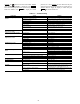
Alarms and Alerts — These are warnings of abnormal
or fault conditions, and may cause either one circuit or the
whole unit to shut down. They are assigned code numbers as
described in Table 34.
Automatic alarms will reset without operator intervention if
the condition corrects itself. The following method must be
used to reset manual alarms:
Before resetting any alarm, first determine the cause of the
alarm and correct it. Enter the Alarms mode indicated by the
LED on the side of the scrolling marquee display. Press
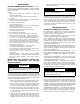
CAUTION
Restoring the compressor sooner may cause a destructive
temperature build up in the scrolls.
CAUTION
The motor protection system within the compressor is now
bypassed. Use this configuration to temporarily test mod-
ule only. Failure to do this may result in unit damage.
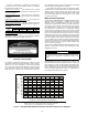
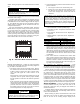
Fig. 45 — Electronic Motor Protection Module
a30-5526
IMPORTANT: Use an ohmmeter with a maximum of 9
volts to check the sensor chain. The sensor chain is sensi-
tive and easily damaged; no attempt should be made to
check continuity through it with anything other than an
ohmmeter. The application of any external voltage to the
sensor chain may cause damage requiring the replacement
of the compressor.
Motor Protector PTC Key Values
Normal PTC resistance: 250 to 2250 Ohms
Trip resistance: >4500 Ohm ± 20%
Reset resistance: <2750 Ohm ± 20%