
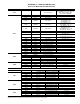
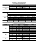
Specifications

76
T170 (Loss of Communication with the Compressor Expan-
sion Module) —This alert indicates that there are communica-
tions problems with the compressor expansion module. All
functions performed by the CXB will stop. The alarm will au-
tomatically reset.
A172 (Loss of Communication with the EXV Board)
—
This alarm indicates that there are communications problems
with the EXV board. The alarm will automatically reset.
T173 (Energy Management Module Communication Fail-
ure) — This alert indicates that there are communications
problems with the energy management. All functions per-
formed by the EMM will stop, which can include demand lim-
it, reset and capacity input. The alarm will automatically reset.
T174 (4 to 20 mA Cooling Set Point Input Failure)
— This
alert indicates a problem has been detected with cooling set
point 4 to 20 mA input. The input value is either less than 2 mA
or greater than 22 mA.
T175 (Loss of Communication with the AUX Board)
—
This alarm indicates that there are communications problems
with the AUX board. All functions performed by the AUX
board will stop, which can include digital scroll unloader oper-
ation and low ambient head pressure control. The alarm will
automatically reset.
T176 (4 to 20 mA Reset Input Failure)
— This alert indi-
cates a problem has been detected with reset 4 to 20 mA input.
The input value is either less than 2 mA or greater than 22 mA.
The reset function will be disabled when this occurs.
T177 (4 to 20 mA Demand Limit Input Failure)
— This
alert indicates a problem has been detected with demand limit
4 to 20 mA input. The input value is either less than 2 mA or
greater than 22 mA. The reset function will be disabled when
this occurs.
P200 — Cooler Flow/Interlock Contacts Failed to Close at
Start-Up Pre-Alert
A200 — Cooler Flow/Interlock Contacts Failed to Close at
Start-Up Alarm — These alarms will occur if the cooler flow
switch/cooler pump interlock contacts failed to close within 1
minute after start-up, if cooler pump control is enabled; or
within 5 minutes after start-up, if cooler pump control is not en-
abled. If the unit is equipped with dual pumps, the second
pump will be started and time allowed to prove flow before the
unit is alarmed. When this alarm occurs, the chiller is not al-
lowed to start. The alarm will require manual reset.
If this condition is encountered, check the following items:
• chilled water flow switch, for proper operation
• flow switch cable, for power and control
• check the chilled water loop to be sure that it is com-
pletely filled with water, and all air has been purged
• chilled water pump interlock circuit, for proper operation
• pump electrical circuit for power
• pump circuit breaker
• pump contactor, for proper operation
• hilled water pump, for proper operation; look for over-
load trips
• chilled water strainer for a restriction
• make sure that all isolation valves are open completely
P201 — Cooler Flow/Interlock Contacts Opened During
Normal Operation Pre-Alert
A201 — Cooler Flow/Interlock Contacts Opened During
Normal Operation Alarm — If the chilled water flow switch
opens for at least three (3) seconds after initially being closed, a
P201 — Cooler Flow/Interlock Contacts Opened During Nor-
mal Operation Pre-Alert will be generated for the appropriate
pump and the machine will stop. If available, the other pump
will be started. If flow is proven, the machine will be allowed
to restart. If after 5 minutes, the cooler flow switch/interlock
contacts do not close, the alarm will change to an A201 —
Cooler Flow/Interlock Contacts Opened During Normal Oper-
ation Alarm.
When this alarm occurs, the chiller will be shut down. The
pre-alert (P201) will be reset automatically; the alarm (A201)
will require manual reset.
Possible Causes:
If this condition is encountered, check the following items:
• chilled water flow switch, for proper operation.
• flow switch cable, for power and control.
• check the chilled water loop to be sure that it is com-
pletely filled with water, and all air has been purged.
• check the chilled water pump interlock circuit for proper
operation.
In units that do not control the chilled water pump, check
the Cooler Pump Shutdown Delay (Configura-
tion
OPT1
PM.DY). The factory default is set to one min-
ute. If the unit is signaled to stop and the pumps are shutdown
shortly after the command, this alarm may trigger. Try setting
the delay to 0. Look at the system operation sequence to be
sure that the unit has enough time to shut down, before the
chilled water flow stops. Check the following items:
• pump electrical circuit for power.
• pump circuit breaker.
• pump contactor, for proper operation.
• chilled water pump for proper operation; look for over-
load trips.
• chilled water strainer for a restriction.
• make sure that all isolation valves are open completely.
T206 — High Leaving Chilled Water Temperature Alert
—
This alert will be generated if the unit is at 100% capacity for at
least 60 seconds and the Leaving Water Temperature, LW T
(Run Status
VIEW) is greater than the Control Point, CTPT
(Run Status
VIEW) plus the High Leaving Chilled Water
Alert Limit, LCWT (Configuration
OPT2).
LW T > C T P T + LC W T
LCWT is field selectable from 2 to 60 ΔF (1.1 to 33.3 ΔC)
and is defaulted at 60 ΔF (33.3 ΔC).
The unit will not generate this alert if Capacity, CAP (Run
Status
VIEW) is less than 100%. If the unit's available capac-
ity is less than 100%, this alert will not be generated.
No action will be taken; this is an alert only.
This alert will reset automatically if one of two conditions is
met:
1. If the Leaving Water Temperature, LW T (Run Sta-
tus
VIEW) is less than the Control Point, CTPT (Run
Status
VIEW) plus the High Leaving Chilled Water
Alert Limit, LCWT (Configuration
OPT2) minus 5° F
(2.8° C).
LW T < C T P T + LC W T – 5° F (2.8° C)
2. If the Leaving Water Temperature, LW T (Run Sta-
tus
VIEW) is less than the Control Point, CTPT (Run
Status
VIEW).
LW T < C T P T
If this condition is encountered, check to be sure building
load does not exceed unit capacity.
T501, T502, T503 (Current Sensor Board Failure — A xx
Circuit A)
T505, T506, T507 (Current Sensor Board Failure — B xx
Circuit B) — Alert codes T501-T503 are for compressors A1-
A3, respectively, and T505-T507 are for compressors B1-B3,
respectively. These alerts occur when the output of the CSB is a
constant high value. These alerts reset automatically. If the
problem cannot be resolved, the CSB must be replaced.