AQUASNAP® 30MPA,MPW015-045 Liquid Chillers with Scroll Compressors and ComfortLink™ Controls Controls, Start-Up, Operation, Service, and Troubleshooting SAFETY CONSIDERATIONS Installing, starting up, and servicing this equipment can be hazardous due to system pressures, electrical components, and equipment location (elevated structures, mechanical rooms, etc.). Only trained, qualified installers and service mechanics should install, start up, and service this equipment.
• MINIMUM LOAD VALVE • PRESSURE RELIEF DEVICES Check Unit Safeties . . . . . . . . . . . . . . . . . . . . . . . . . . . . . . . . Thermistors. . . . . . . . . . . . . . . . . . . . . . . . . . . . . . . . . . . . . . . . Pressure Transducers . . . . . . . . . . . . . . . . . . . . . . . . . . . . . Chilled Water Flow Switch . . . . . . . . . . . . . . . . . . . . . . . . . Strainer . . . . . . . . . . . . . . . . . . . . . . . . . . . . . . . . . . . . . . . . . . . . CONTENTS Page SAFETY CONSIDERATIONS.
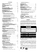
Changing item values or testing outputs is accomplished in the same manner. Locate and display the desired item. Press ENTER so that the item value flashes. Use the arrow keys to change the value or state and press the ENTER key to accept it. Press the ESCAPE key to return to the next higher level of structure. Repeat the process as required for other items. When a value is included as part of the path name, it will be shown at the end of the path name after an equals sign.
Configuration mode. Press ENTER to obtain access to this mode. The display will read: > TEST OFF METR OFF LANG ENGLISH Pressing ENTER will cause the “OFF” to flash. Use the up or down arrow keys to change “OFF” to “ON”. Pressing ENTER will illuminate all LEDs and display all pixels in the view screen. Pressing the up and down arrow keys simultaneously allows the user to adjust the display brightness. Use the up or down arrow keys to adjust screen brightness. Press ENTER to accept the change.
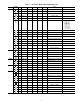
Table 3 — Run Status Mode and Sub-Mode Directory SUB-MODE KEYPAD ENTRY ITEM DISPLAY VIEW ENTER EWT XXX.X F ENTERING FLUID TEMP LWT XXX.X F LEAVING FLUID TEMP SETP XXX.X F ACTIVE SETPOINT CTPT XXX.X F CONTROL POINT LOD.F XXX LOAD/UNLOAD FACTOR STAT X CONTROL MODE OCC YES/NO OCCUPIED MODE YES/NO OVERRIDE MODES IN EFFECT CAP XXX % PERCENT TOTAL CAPACITY STGE X REQUESTED STAGE ALRM XXX CURRENT ALARMS & ALERTS TIME XX.XX TIME OF DAY 00.00-23.
Table 3 — Run Status Mode and Sub-Mode Directory (cont) SUB-MODE KEYPAD ENTRY ITEM VERS ENTER *Press ENTER and ITEM EXPANSION COMMENT AUX CESR131333-xx-xx xx-xx is Version number* MBB CESR131279-xx-xx xx-xx is Version number* EMM CESR131174-xx-xx xx-xx is Version number* MARQ CESR131171-xx-xx xx-xx is Version number* NAVI CESR130227-xx-xx xx-xx is Version number* ESCAPE DISPLAY SUB-ITEM DISPLAY SUB-ITEM DISPLAY simultaneously to obtain version number.
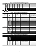
Table 5 — Temperature Mode and Sub-Mode Directory (cont) SUB-MODE KEYPAD ENTRY ITEM DISPLAY ITEM EXPANSION TEMPERATURES CIRCUIT A ENTER SCT.A XXX.X F SATURATED CONDENSING TMP SST.A XXX.X F SATURATED SUCTION TEMP RGT.A XXX.X F COMPR RETURN GAS TEMP D.GAS XXX.X F DISCHARGE GAS TEMP SH.A XXX.X ^F SUCTION SUPERHEAT TEMP CIR.A COMMENT Table 6 — Pressure Mode and Sub-Mode Directory SUB-MODE KEYPAD ENTRY ITEM DISPLAY ITEM EXPANSION PRESSURES CIRCUIT A ENTER DP.A XXX.
Table 9 — Outputs Mode and Sub-Mode Directory SUB-MODE KEYPAD ENTRY ITEM DISPLAY ITEM EXPANSION GENERAL OUTPUTS ENTER C.LWP ON/OFF COOLER PUMP RELAY C.DWP ON/OFF CONDENSER PUMP ALRM ON/OFF ALARM RELAY CDWO ON/OFF CONDENSER VALVE OPEN CDWC ON/OFF GEN.O COMMENT CONDENSER VALVE CLOSE CIR.A OUTPUTS CIRCUIT A ENTER CC.A1 ON/OFF COMPRESSOR A1 RELAY D.SOL ON/OFF DIGITAL SCROLL SOLENOID CC.A2 ON/OFF COMPRESSOR A2 RELAY CC.
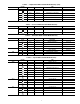
Table 10 — Configuration Mode and Sub-Mode Directory (cont) SUB-MODE KEYPAD ENTRY ITEM DISPLAY ENTER FLUD X COOLER FLUID MLV.S YES/NO MINIMUM LOAD VALVE SELECT R.G.EN ENBL/DSBL RETURN GAS SENSOR ENABLE OAT.E ENBL/DSBL ENABLE OAT SENSOR D.G.EN ENBL/DSBL DISCHARGE GAS TEMP ENABLE CSB.E ENBL/DSBL CSB BOARDS ENABLE CPC ON/OFF COOLER PUMP CONTROL PM.
Table 10 — Configuration Mode and Sub-Mode Directory (cont) SUB-MODE RSET (cont) KEYPAD ENTRY ITEM DISPLAY ITEM EXPANSION LLEN ENBL/DSBL LEAD/LAG CHILLER ENABLE MSSL SLVE/MAST MASTER/SLAVE SELECT Default: Master Default: 0 Range: 0 to 239 Default: Disable SLVA XXX SLAVE ADDRESS LLBL X LEAD/LAG BALANCE SELECT LLBD XXX LEAD/LAG BALANCE DELTA LLDY XXX LAG START DELAY PARA YES PARALLEL CONFIGURATION CLSP X SETPOINT AND RAMP LOAD COOLING SETPOINT SELECT RL.
Table 11 — Time Clock Mode and Sub-Mode Directory SUB-MODE KEYPAD ENTRY ITEM DISPLAY ENTER HH.MM XX.XX SUB-ITEM ITEM EXPANSION TIME OF DAY DISPLAY TIME HOUR AND MINUTE DATE COMMENT Military (00:00 – 23:59) MONTH,DATE,DAY AND YEAR ENTER MNTH XX MONTH OF YEAR 1-12 (1 = January, 2 = February, etc) DOM XX DAY OF MONTH Range: 01-31 DAY X DAY OF WEEK 1-7 (1 = Monday, 2 = Tuesday, etc) YEAR XXXX YEAR OF CENTURY STR.M XX MONTH Default: 4, Range 1 – 12 STR.
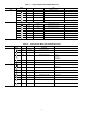
Table 12 — Operating Mode and Sub-Mode Directory SUB-MODE KEYPAD ENTRY ITEM DISPLAY ITEM EXPANSION MODES CONTROLLING UNIT ENTER MD01 ON/OFF CSM CONTROLLING CHILLER MD03 ON/OFF MASTER/SLAVE CONTROL MD05 ON/OFF RAMP LOAD LIMITED MD06 ON/OFF TIMED OVERRIDE IN EFFECT MD07 ON/OFF LOW COOLER SUCTION TEMPA MD09 ON/OFF SLOW CHANGE OVERRIDE MD10 ON/OFF MINIMUM OFF TIME ACTIVE MD13 ON/OFF DUAL SETPOINT MD14 ON/OFF TEMPERATURE RESET MD15 ON/OFF DEMAND LIMITED MD16 ON/OFF COOLER FR
Table 14 — Operating Modes MODE NO. ITEM EXPANSION 01 CSM CONTROLLING CHILLER 03 MASTER/SLAVE CONTROL Ramp load (pull-down) limiting in effect. In this mode, the rate at which leaving fluid temperature is dropped is limited to a predetermined value to prevent compressor overloading. See Cooling Ramp Loading (ConfigurationSLCTCRMP). The pull-down limit can be modified, if desired, to any rate from 0.2° F to 2° F (0.1° to 1° C)/minute. TIMED OVERRIDE IN EFFECT Timed override is in effect.
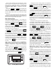
the main base board (MBB) is supplied with the current software. If necessary, reload current software. If the problem still persists, replace the MBB. A red LED that is lit continuously or blinking at a rate of once per second or faster indicates that the board should be replaced. GREEN LED — The MBB has one green LED. The Local Equipment Network (LEN) LED should always be blinking whenever power is on. All other boards have a LEN LED which should be blinking whenever power is on.
LEGEND FOR FIG.
EQUIP GND TB3 UPC LON OPTION UPC 25 24 23 22 21 20 19 18 17 16 15 14 13 12 11 10 9 8 7 6 5 4 3 2 1 LVT DISCONNECT OPTION CB1A/TB1A L1 L2 L3 CCB-1 CCB-2 CCB-3 EMM CSB-A1 2 4 CSB-A2 CSB-A3 6 CCH CA1 CA2 CA3 TRAN1 MBB FB1 LOCATED OVER EMM CB1 CB2 CB3 REMOTE CONTROL SW1 OFF ENABLE Fig.
TO FUSED DISCONNECT PER NEC 17 RED B1 A1 SW2 XF FU3 VIO VIO 380V ONLY CB3 3.
TRAN1 A2 CB2 3.
RGTA, CNDE, CNDL, EWT, LWT, and OAT are identical in temperature versus resistance and voltage drop performance. The dual chiller thermistor (DLWT) is 5 k at 77 F (25 C) thermistor. Space temperature thermistor (SPT) is a 10 kat 77 F (25 C). See Thermistors section for temperature-resistance-voltage drop characteristics. COOLER LEAVING FLUID SENSOR (LWT) — The thermistor is installed in a well in the factory-installed leaving fluid piping coming from the bottom of the brazed-plate heat exchanger.
RED LED - STATUS GREEN LED LEN (LOCAL EQUIPMENT NETWORK) YELLOW LED CCN (CARRIER COMFORT NETWORK) INSTANCE JUMPER CEPL130346-01 K11 J1 J4 K8 STATUS J2 K7 K10 K9 K5 K6 J10 LEN J3 K4 K3 K1 K2 CCN J5 J6 J7 J9 J8 Fig. 6 — Main Base Board a30-4967 Fig. 7 — Enable/Off/Remote Contact Switch, and Emergency On/Off Switch Locations T-55 SPACE SENSOR a30-4968 SPT (T10) PART NO.
stages. The chilled fluid temperature set point can be automatically reset by the return fluid temperature, space, or outdoor-air temperature reset features. It can also be reset from an external 4 to 20-mA signal (requires energy management module FIOP or accessory). The capacity control algorithm runs every 30 seconds. The algorithm attempts to maintain the Control Point at the desired set point. Each time it runs, the control reads the entering and leaving fluid temperatures.
Slow Change Override — The control prevents the capacity stages from being changed when the leaving fluid temperature is close to the set point (within an adjustable deadband) and moving towards the set point. First Stage Override — If the current capacity stage is zero, the control will modify the routine with a 1.2 factor on adding the first stage to reduce cycling. This factor is also applied when the control is attempting to remove the last stage of capacity.
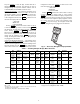
2 STARTS DEADBAND EXAMPLE 47 7 6 46 45 LWT (F) LWT (C) 8 44 43 42 5 41 0 200 400 600 800 1000 3 STARTS TIME (SECONDS) LEGEND LWT — Leaving Water Temperature STANDARD DEADBAND MODIFIED DEADBAND Fig. 11 — Deadband Multiplier 170 160 150 140 130 SCT (F) 120 110 100 90 80 70 60 50 40 30 -30 -20 -10 0 10 30 40 50 60 70 80 SST (F) LEGEND SCT SST 20 a30-4969 — Saturated Condensing Temperature — Saturated Suction Temperature Fig.
may be entered for systems with brine solutions, but this value should be set according to the freeze protection level of the brine mixture. Failure to properly set this brine freeze point value may permanently damage the brazed plate heat exchanger. The control will initiate Mode 7 (Circuit A) to indicate a circuit’s capacity is limited and that eventually the circuit may shut down. Cooling Set Point Select SINGLE — Unit operation is based on Cooling Set Point 1 (Set PointsCOOLCSP.1).
Test the condenser output, cooler pump, liquid line solenoid valve (30MPA only), crankcase heater, water valve (accessory), and alarm relay by changing the item values from OFF to ON. These discrete outputs are then turned off if there is no keypad activity for 10 minutes. When testing compressors, lead compressor must be started first. All compressor outputs can be turned on, but the control will limit the rate by staging one compressor per minute.
Table 21 — Dual Chiller Configuration (Master Chiller Example) SUB-MODE ITEM KEYPAD ENTRY DISPLAY ITEM EXPANSION COMMENTS ENTER CTRL CONTROL METHOD ENTER 0 SWITCH DEFAULT 0 ESCAPE OPT2 CCN ADDRESS DEFAULT 1 CCN BUS NUMBER DEFAULT 0 DISP UNIT OPT1 OPT2 CTRL CCN CCNA ENTER 1 CCNB CCN CCNB ENTER 0 ESCAPE CCN PROCEED TO SUBMODE RESET RSET RSET ENTER LLEN LLEN MSSL CRST COOLING RESET TYPE LLEN LEAD/LAG CHILLER ENABLE ENTER DSBL SCROLLING STOPS ENTER DSBL VALUE FLASHES
Table 21 — Dual Chiller Configuration (Master Chiller Example) (cont) SUB-MODE RSET ITEM KEYPAD ENTRY DISPLAY ITEM EXPANSION COMMENTS LLBL ENTER 2 LEAD/LAG BALANCE SELECT CHANGE ACCEPTED ESCAPE LLBL LLBD LLBD LEAD/LAG BALANCE DELTA ENTER 168 LEAD/LAG BALANCE DELTA ESCAPE LLBD LLDY LLDY LLDY PARA DEFAULT 168 LAG START DELAY ENTER 5 SCROLLING STOPS ENTER 5 VALUE FLASHES 10 SELECT 10 ENTER 10 ESCAPE LLDY ESCAPE RSET ENTER YES LAG START DELAY CHANGE ACCEPTED MASTER CO
Table 22 — Dual Chiller Configuration (Slave Chiller Example) SUB-MODE ITEM KEYPAD ENTRY DISPLAY ITEM EXPANSION COMMENTS ENTER CTRL CONTROL METHOD 0 SWITCH DEFAULT 0 CCN ADDRESS SCROLLING STOPS DISP UNIT OPT1 OPT2 CTRL ESCAPE OPT2 CCN CCNA CCNA ENTER 1 ENTER 1 VALUE FLASHES 2 SELECT 2 (SEE NOTE 2) CCN CCNA CCNB ENTER 2 ESCAPE CCN ENTER 0 ESCAPE CCN CCN ADDRESS CHANGE ACCEPTED CCN BUS NUMBER DEFAULT 0 (SEE NOTE 3) PROCEED TO SUBMODE RSET RSET RSET ENTER LLEN LLEN
Table 23 — Menu Configuration of 4 to 20 mA Cooling Set Point Control MODE (RED LED) KEYPAD SUB-MODE KEYPAD ENTRY ENTRY ITEM DISPLAY ITEM EXPANSION CLSP 0 COOLING SETPOINT SELECT COMMENT DISP ENTER UNIT OPT1 OPT2 CCN CONFIGURATION RSET SLCT ENTER ENTER 0 Scrolling Stops ENTER 0 Flashing ‘0’ 3 Select ‘3’ 3 Change Accepted ENTER Table 24 — 4 to 20 mA Reset SUB-MODE KEYPAD ENTRY DISPLAY ITEM EXPANSION CRST 1 COOLING RESET TYPE MA.DG 5.0 F (2.
Table 25 — Configuring Outdoor Air and Space Temperature Reset MODE (RED LED) KEYPAD ENTRY SUBMODE ENTER DISP KEYPAD ENTRY DISPLAY ITEM Outdoor Air Space ITEM EXPANSION COMMENT CRST 2 4 COOLING RESET TYPE 2 = Outdoor-Air Temperature (Connect to LVT-4,5) 4 = Space Temperature (Connect to LVT-3,4) RM.NO* 85 °F 72 °F REMOTE - NO RESET TEMP Default: 125.0 F (51.7 C) Range: 0° to125 F RM.F 55 °F 68 °F REMOTE - FULL RESET TEMP Default: 0.0° F (-17.7 C) Range: 0° to 125 F RM.
LWT LWT Under normal operation, the chiller will maintain a constant leaving fluid temperature approximately equal to the chilled fluid set point. As the cooler load varies, the entering cooler fluid will change in proportion to the load as shown in Fig. 17. Usually the chiller size and leaving-fluid temperature set point are selected based on a full-load condition. At part load, the fluid temperature set point may be colder than required.
length of time that a loadshed condition is allowed to exist. The control will disable the Redline/Loadshed command if no Cancel command has been received within the configured maximum loadshed time limit. DEMAND LIMIT (CCN Loadshed Controlled) — To configure Demand Limit for CCN Loadshed control set the Demand Limit Select (ConfigurationRSETDMDC) to 3.
Table 27 — Configuring Demand Limit MODE CONFIGURATION KEYPAD ENTRY SUB-MODE KEYPAD ENTRY ITEM DISPLAY ITEM EXPANSION ENTER DISP ENTER TEST ON/OFF Test Display LEDs UNIT ENTER TYPE X Unit Type OPT1 ENTER FLUD X Cooler Fluid OPT2 ENTER CTRL X Control Method CCN ENTER CCNA X CCN Address RSET ENTER CRST X Cooling Reset Type COMMENT Default: 0 0 = None 1 = Switch 2 = 4 to 20 mA Input 3 = CCN Loadshed DMDC* X Demand Limit Select DM20 XXX % Demand Limit at 20 mA Defau
All refrigerant charging should be done through the ¼-in. Schraeder connection on the liquid line. Do NOT add refrigerant charge through the low-pressure side of the system. If complete charging is required, weigh in the appropriate charge for the circuit as shown on the unit nameplate. If partial charging is required, operate circuit at full load and add charge until the sight glass is clear of bubbles. a30-4978 CAUTION Never charge liquid into low-pressure side of system. Do not overcharge.
medium temperature brine unit, the cooler LCWT can go down to 15 F (–9.4 C). LIQUID CHARGING METHOD — Add charge to the unit through the liquid line service valve. Never charge liquid into the low-pressure side of the system. 1. Close liquid line ball valve (30MPA only). 2. Connect a refrigerant cylinder loosely to the high flow Schraeder valve connection on the liquid line. Purge the charging hose and tighten the connections. 3. Open the refrigerant cylinder valve. 4.
mounting hardware. Using new tubing as required, reconnect compressor suction and discharge lines. Using hardware saved, reinstall the mounting bolts and washers through the compressor feet. Using proper techniques, braze suction and discharge lines and check for leaks. Reconnect oil equalization line. Re-install the crankcase heater (30MPA units). Reconnect the compressor power connections and high-pressure switch wiring as on the old compressor. Refer to Fig. 21.
The strainers in front of the water/brine inlets of the heat exchangers should be cleaned periodically, depending on condition of the chiller water/brine. Do not reuse oil that has been drained out, or oil that has been exposed to atmosphere. Oil Charge FILTER DRIER — The function of the filter drier is to maintain a clean, dry system. The moisture indicator (described below) indicates any need to change the filter drier. The filter drier is a sealed-type drier.
COOLER FREEZE-UP PROTECTION MINIMUM LOAD VALVE — On units equipped with the factory-installed hot gas bypass option, a solenoid valve and discharge bypass valve (minimum load valve) are located between the discharge line and the cooler entering-refrigerant line. The MBB cycles the solenoid to perform minimum load valve function and the discharge bypass valve modulates to the suction pressure set point of the valve. The bypass valve has an adjustable opening setting between 95 to 115 psig (655 to 793 kPa).
4. Wrong pump motor rotation. Pump must rotate clockwise when viewed from motor end of pump. gauge. Pressure readings should be within ± 15 psig. If the two readings are not reasonably close, replace the pressure transducer. Chilled Water Flow Switch — A factory-installed 1 flow switch is installed in the leaving fluid piping for all units. This is a thermal-dispersion flow switch with no field adjustments. The switch is set for approximately 0.5 ft/sec of flow.
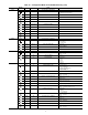
Table 32 — 5K Thermistor Temperatures (°F) vs. Resistance/Voltage Drop (Voltage Drop for EWT, LWT, RGT, CNDE, CNDL, Dual Chiller, and OAT) TEMP (F) –25 –24 –23 –22 –21 –20 –19 –18 –17 –16 –15 –14 –13 –12 –11 –10 –9 –8 –7 –6 –5 –4 –3 –2 –1 0 1 2 3 4 5 6 7 8 9 10 11 12 13 14 15 16 17 18 19 20 21 22 23 24 25 26 27 28 29 30 31 32 33 34 35 36 37 38 39 40 41 42 43 44 45 46 47 48 49 50 51 52 53 54 55 56 57 58 VOLTAGE DROP (V) 3.699 3.689 3.679 3.668 3.658 3.647 3.636 3.624 3.613 3.601 3.588 3.576 3.563 3.550 3.
Table 33 — 5K Thermistor Temperatures (°C) vs. Resistance/Voltage Drop (Voltage Drop for EWT, LWT, RGT, CNDE, CNDL, Dual Chiller, and OAT) TEMP (C) –32 –31 –30 –29 –28 –27 –26 –25 –24 –23 –22 –21 –20 –19 –18 –17 –16 –15 –14 –13 –12 –11 –10 –9 –8 –7 –6 –5 –4 –3 –2 –1 0 1 2 3 4 5 6 7 8 9 10 11 12 13 14 VOLTAGE DROP (V) 3.705 3.687 3.668 3.649 3.629 3.608 3.586 3.563 3.539 3.514 3.489 3.462 3.434 3.406 3.376 3.345 3.313 3.281 3.247 3.212 3.177 3.140 3.103 3.065 3.025 2.985 2.945 2.903 2.860 2.817 2.774 2.
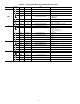
Table 34 — 10K Thermistor Temperature (°F) vs. Resistance/Voltage Drop (For SPT) TEMP (F) –25 –24 –23 –22 –21 –20 –19 –18 –17 –16 –15 –14 –13 –12 –11 –10 –9 –8 –7 –6 –5 –4 –3 –2 –1 0 1 2 3 4 5 6 7 8 9 10 11 12 13 14 15 16 17 18 19 20 21 22 23 24 25 26 27 28 29 30 31 32 33 34 35 36 37 38 39 40 41 42 43 44 45 46 47 48 49 50 51 52 53 54 55 56 57 58 59 60 VOLTAGE DROP (V) 4.758 4.750 4.741 4.733 4.724 4.715 4.705 4.696 4.686 4.676 4.665 4.655 4.644 4.633 4.621 4.609 4.597 4.585 4.572 4.560 4.546 4.533 4.519 4.
Table 35 — 10K Thermistor Temperature (°C) vs. Resistance/Voltage Drop (For SPT) TEMP (C) –32 –31 –30 –29 –28 –27 –26 –25 –24 –23 –22 –21 –20 –19 –18 –17 –16 –15 –14 –13 –12 –11 –10 –9 –8 –7 –6 –5 –4 –3 –2 –1 0 1 2 3 4 5 6 7 8 9 10 11 12 13 14 VOLTAGE DROP (V) 4.762 4.748 4.733 4.716 4.700 4.682 4.663 4.644 4.624 4.602 4.580 4.557 4.533 4.508 4.482 4.455 4.426 4.397 4.367 4.335 4.303 4.269 4.235 4.199 4.162 4.124 4.085 4.044 4.003 3.961 3.917 3.873 3.828 3.781 3.734 3.686 3.637 3.587 3.537 3.485 3.433 3.
UNIT ENABLE-OFF-REMOTE CONTACT SWITCH IS OFF — When the switch is OFF, the unit will stop immediately. Place the switch in the ENABLE position for local switch control or in the REMOTE CONTACT position for control through remote contact closure. CHILLED FLUID PROOF-OF-FLOW SWITCH OPEN — After the problem causing the loss of flow has been corrected, reset is manual by resetting the alarm with the scrolling marquee. OPEN 24-V CONTROL CIRCUIT BREAKER(S) — Determine the cause of the failure and correct.
the compressor is commanded OFF and the current sensor reads ON, an alert is generated. This will indicate that a compressor contactor has failed closed. In this case, a special mode, Compressor Stuck on Control, will be enabled and all other compressors will be turned off. An alarm will then be enabled to indicate that service is required. Outdoor fans will continue to operate. The condenser output is turned on immediately.
Table 37 — Troubleshooting SYMPTOMS Compressor Cycles Off on Loss of Charge Compressor Cycles Off on Out of Range Condition Compressor Shuts Down on High-Pressure Control Unit Operates Too Long or Continuously Unusual or Loud System Noises CAUSE Loss of charge control. Acting erratically.
Table 38 — Alarm and Alert Codes ALARM/ ALERT CODE ALARM OR ALERT A048 Alarm Circuit A Compressor Availability Alarm Two compressors on circuit failed Circuit shut down Manual Only one compressor operating. T051 Alert Circuit A, Compressor 1 Failure Compressor feedback signal does not match relay state Compressor A1 shut down. Manual High-pressure switch open, faulty CSB, loss of condenser flow, filter drier plugged, noncondensables, operation beyond capability.
Table 38 — Alarm and Alert Codes (cont) ALARM/ ALERT CODE ALARM OR ALERT A116 Alarm A122 Alarm DESCRIPTION Circuit A Low Cooler Suction Temperature High Pressure Switch Trip Circuit A WHY WAS THIS ALARM GENERATED? ACTION TAKEN BY CONTROL Mode 7 caused the compressor to unload 6 consecutive times with less than a Circuit shut down 30-minute interval between each circuit shutdown.
Table 38 — Alarm and Alert Codes (cont) ALARM/ ALERT CODE T200 A201 A202 T203 T204 T205 T206 ALARM OR ALERT DESCRIPTION WHY WAS THIS ALARM GENERATED? Alert Cooler Flow/Interlock Contacts failed to Close at start-up Cooler flow switch contacts failed to close within 1 minute (if cooler pump control is enabled) or within 5 minutes (if cooler pump control is not enabled) after start-up Alarm Cooler Flow/Interlock Contacts Opened During Normal Operation RESET METHOD PROBABLE CAUSE Chiller not
Table 38 — Alarm and Alert Codes (cont) ALARM/ ALERT CODE ALARM OR ALERT DESCRIPTION WHY WAS THIS ALARM GENERATED? ACTION TAKEN BY CONTROL RESET METHOD Strainer Service Countdown (S.T.DN) expired. Complete strainer blowdown and enter 'YES' for Strainer Maintenance Done (S.T.MN) item.
been commanded OFF. This is done to facilitate a service technician forcing a relay to test a compressor. In addition, if a compressor stuck failure occurs and the current sensor board reports the compressor and the request off, certain diagnostics will take place as follows: 1. If any of the compressors are diagnosed as stuck on and the current sensor board is on and the request is off, the control will command the condenser fans to maintain normal head pressure. 2.
This is done to make a rough calibration of the high pressure switch trip point. In most cases this allows the control to detect a high head pressure condition prior to reaching the high pressure switch trip point. When the trip occurs, all mechanical cooling on the circuit is shut down for 15 minutes. After 15 minutes, the circuit is allowed to restart.
APPENDIX A — LOCAL DISPLAY TABLES Run Status Mode and Sub-Mode Directory SUB-MODE VIEW RUN HOUR STRT PM VERS ITEM DISPLAY CCN POINT xxx x xxx xx.xx ITEM DESCRIPTION AUTO VIEW OF RUN STATUS Entering Fluid Temp Leaving Fluid Temp Active Setpoint Control Point Load/Unload Factor Control Mode Occupied Override Modes in Effect Percent Total Capacity Requested Stage Current Alarms & Alerts Time of Day EWT LWT SETP CTPT LOD.F STAT OCC xxx.x ºF xxx.x ºF xxx.x ºF xxx.
APPENDIX A — LOCAL DISPLAY TABLES (cont) Service Test Mode and Sub-Mode Directory SUB-MODE ITEM TEST OUTS CMPA DISPLAY ITEM DESCRIPTION CCN POINT ON/OFF Service Test Mode MAN_CTRL CLR.P CND.P UL.TM CC.H CW.VO CW.VC LL.SV RMT.A OFF/ON OFF/ON xx OFF/ON OFF/ON OFF/ON OFF/ON OFF/ON CC.A1 UL.TM CC.A2 CC.A3 MLV OFF/ON xx OFF/ON OFF/ON OFF/ON COMMENT To enable Service Test mode, move Enable/Off/Remote contact switch to OFF. Change TEST to ON.
APPENDIX A — LOCAL DISPLAY TABLES (cont) Set Points Mode and Sub-Mode Directory SUB-MODE COOL HEAD FRZ ITEM DISPLAY CSP.1 CSP.2 CSP.3 xxx.x °F xxx.x °F xxx.x °F H.DP xxx.x °F BR.FZ xx.
APPENDIX A — LOCAL DISPLAY TABLES (cont) Configuration Mode and Sub-Mode Directory SUB-MODE DISP UNIT OPT1 OPT2 ITEM DISPLAY TEST METR OFF/ON OFF/ON LANG X PAS.E PASS DSBL/ENBL XXXX TYPE X SIZE SZA.1 SZA.2 SZA.3 A1.TY MAX.T XXX XX XX XX NO/YES XX FLUD X MLV.S RG.EN OAT.E D.G.EN CSB.E CPC PM.DY DPME DFLS CDWS NO/YES DSBL/ENBL DSBL/ENBL DSBL/ENBL DSBL/ENBL OFF/ON XX MIN X DSBL/ENBL DSBL/ENBL CTRL X LCWT DELY ICE.
APPENDIX A — LOCAL DISPLAY TABLES (cont) Configuration Mode and Sub-Mode Directory (cont) SUB-MODE ITEM DISPLAY ITEM DESCRIPTION RESET COOL TEMP CCN POINT CRST X Cooling Reset Type CRST_TYP MA.DG RM.NO RM.F RM.DG RT.NO RT.F RT.DG XX.XΔF XXX.X °F XXX.X °F XX.X °F XXX.XΔF XXX.XΔF XX.
APPENDIX A — LOCAL DISPLAY TABLES (cont) Time Clock Mode and Sub-Mode Directory SUB-MODE TIME DATE ITEM DISPLAY ITEM DESCRIPTION CCN POINT TIME OF DAY Hour and Minute TIME MONTH, DATE, DAY, AND YEAR HH.MM XX.XX MNTH XX Month of Year DOM XX Day of Month DOM DAY X Day of Week DOWDISP YEAR XXXX YOCDISP STR.M STR.W STR.D XX X X Year of Century DAYLIGHT SAVINGS TIME Month Week Day MIN.A XX Minutes to Add MINADD MOY STARTM STARTW STARTD DST STP.M XX Month STOPM STP.W STP.
APPENDIX A — LOCAL DISPLAY TABLES (cont) Time Clock Mode and Sub-Mode Directory (cont) SUB-MODE HD.09 HD.10 HD.11 HD.12 HD.13 HD.14 HD.15 HD.16 HD.17 HD.18 HD.
APPENDIX A — LOCAL DISPLAY TABLES (cont) Time Clock Mode and Sub-Mode Directory (cont) SUB-MODE HD.20 HD.21 HD.22 HD.23 HD.24 HD.25 HD.26 HD.27 HD.28 HD.29 HD.
APPENDIX A — LOCAL DISPLAY TABLES (cont) Time Clock Mode and Sub-Mode Directory (cont) SUB-MODE SCH.N SCH.L PER.1 PER.2 PER.3 PER.4 PER.5 ITEM DISPLAY OCC.1 XX:XX UNC.1 XX:XX MON.1 TUE.1 WED.1 THU.1 FRI.1 SAT.1 SUN.1 HOL.1 NO/YES NO/YES NO/YES NO/YES NO/YES NO/YES NO/YES NO/YES OCC.2 XX:XX UNC.2 XX:XX MON.2 TUE.2 WED.2 THU.2 FRI.2 SAT.2 SUN.2 HOL.2 NO/YES NO/YES NO/YES NO/YES NO/YES NO/YES NO/YES NO/YES OCC.3 XX:XX UNC.3 XX:XX MON.3 TUE.3 WED.3 THU.3 FRI.3 SAT.3 SUN.3 HOL.
APPENDIX A — LOCAL DISPLAY TABLES (cont) Time Clock Mode and Sub-Mode Directory (cont) SUB-MODE PER.6 PER.7 PER.8 OVR ITEM DISPLAY OCC.6 XX:XX UNC.6 XX:XX MON.6 TUE.6 WED.6 THU.6 FRI.6 SAT.6 SUN.6 HOL.6 NO/YES NO/YES NO/YES NO/YES NO/YES NO/YES NO/YES NO/YES OCC.7 XX:XX UNC.7 XX:XX MON.7 TUE.7 WED.7 THU.7 FRI.7 SAT.7 SUN.7 HOL.7 NO/YES NO/YES NO/YES NO/YES NO/YES NO/YES NO/YES NO/YES OCC.8 XX:XX UNC.8 XX:XX MON.8 TUE.8 WED.8 THU.8 FRI.8 SAT.8 SUN.8 HOL.
APPENDIX A — LOCAL DISPLAY TABLES (cont) Operating Mode and Sub-Mode Directory SUB-MODE MODE ITEM DISPLAY MD01 MD02 MD03 MD05 MD06 MD07 MD09 MD10 MD13 MD14 MD15 MD16 MD17 MD18 MD19 MD20 MD21 MD23 MD24 OFF/ON OFF/ON OFF/ON OFF/ON OFF/ON OFF/ON OFF/ON OFF/ON OFF/ON OFF/ON OFF/ON OFF/ON OFF/ON OFF/ON OFF/ON OFF/ON OFF/ON OFF/ON OFF/ON ITEM DESCRIPTION CCN POINT MODES CONTROLLING UNIT FSM controlling Chiller MODE_1 WSM controlling Chiller MODE_2 Master/Slave control MODE_3 Ramp Load Limited MODE_5 Timed O
APPENDIX A — LOCAL DISPLAY TABLES (cont) Alarms Mode and Sub-Mode Directory SUB-MODE CRNT RCRN HIST ITEM AA01 AA02 AA03 AA04 AA05 AA06 AA07 AA08 AA09 AA10 AA11 AA12 AA13 AA14 AA15 AA16 AA17 AA18 AA19 AA20 AA21 AA22 AA23 AA24 AA25 NO/YES AL01 AL02 AL03 AL04 AL05 AL06 AL07 AL08 AL09 AL10 AL11 AL12 AL13 AL14 AL15 AL16 AL17 AL18 AL19 AL20 DISPLAY AXXX TXXX PXXX ITEM DESCRIPTION CCN POINT CURRENTLY ACTIVE ALARMS AXXX TXXX PXXX Alarms are shown as AXXX Alerts are shown as TXXX Current Alarms 1-25 Reset
APPENDIX B — CCN TABLES CCN DISPLAY TABLES — A_UNIT (General Unit Parameters DESCRIPTION Control Mode Occupied CCN Chiller Alarm State Active Demand Limit Override Modes in Effect Percent Total Capacity Requested Stage Active Setpoint Control Point Entering Fluid Temp Leaving Fluid Temp Emergency Stop Minutes Left for Start PUMPS Cooler Pump Relay Condenser Pump Cooler Flow Switch VALUE 10-char ASCII No/Yes Stop/Start 6-char ASCII NNN No/Yes NNN NN NNN.n NNN.n NNN.n NNN.
APPENDIX B — CCN TABLES (cont) CCN DISPLAY TABLES — OPTIONS (Unit Parameters) DESCRIPTION UNIT ANALOG VALUES Cooler Entering Fluid Cooler Leaving Fluid Condenser Entering Fluid Condenser Leaving Fluid Lead/Lag Leaving Fluid VALUE UNITS POINT NAME NNN.n NNN.n NNN.n NNN.n NNN.n degF degF degF degF degF COOL_EWT COOL_LWT COND_EWT COND_LWT DUAL_LWT N N N N N TEMPERATURE RESET 4-20 ma Reset Signal Outside Air Temperature Space Temperature NN.n NNN.n NNN.
APPENDIX B — CCN TABLES (cont) CCN MAINTENANCE TABLES — CURRMODS DESCRIPTION CSM controlling Chiller WSM controlling Chiller Master/Slave control Ramp Load Limited Timed Override in effect Low Cooler Suction TempA Slow Change Override Minimum OFF time active Dual Setpoint Temperature Reset Demand Limited Cooler Freeze Protection Low Temperature Cooling High Temperature Cooling Making ICE Storing ICE High SCT Circuit A Minimum Comp.
APPENDIX B — CCN TABLES (cont) CCN MAINTENANCE TABLES — LOADFACT DESCRIPTION CAPACITY CONTROL Load/Unload Factor Control Point Entering Fluid Temp Leaving Fluid Temp VALUE NNN NNN.n NNN.n NNN.n Ramp Load Limited Slow Change Override Cooler Freeze Protection Low Temperature Cooling High Temperature Cooling Minimum Comp.
APPENDIX B — CCN TABLES (cont) CCN MAINTENANCE TABLES — RUNTEST DESCRIPTION Percent Total Capacity Percent Available Cap. Discharge Pressure Suction Pressure Saturated Condensing Tmp Saturated Suction Temp Compr Return Gas Temp Discharge Gas Temp Suction Superheat Temp Compressor A1 Relay Compressor A2 Relay Compressor A3 Relay Minimum Load Valve Relay Compressor A1 Feedback Compressor A2 Feedback Compressor A3 Feedback VALUE NNN NNN NNN.n NNN.n NNN.n NNN.n NNN.n NNN.n NNN.
APPENDIX B — CCN TABLES (cont) CCN CONFIGURATION TABLES — UNIT (Unit Configuration) DESCRIPTION Unit Type Unit Size Compressor A1 Size Compressor A2 Size Compressor A3 Size Suction Superheat Setpt Compressor A1 Digital? Maximum A1 Unload Time VALUE N NNN NNN NNN NNN NN.
APPENDIX B — CCN TABLES (cont) CCN CONFIGURATION TABLES — RESETCON (Temperature Reset and Demand Limit) DESCRIPTION COOLING RESET Cooling Reset Type 4-20 MA RESET 4-20 - Degrees Reset VALUE DEFAULT N UNITS 0 POINT NAME CRST_TYP NNN.n deltaF 420_DEG REMOTE RESET Remote - No Reset Temp Remote - Full Reset Temp Remote - Degrees Reset NNN.n NNN.n NNN.n degF degF deltaF REM_NO REM_FULL REM_DEG RETURN TEMPERATURE RESET Return - No Reset Temp Return - Full Reset Temp Return - Degrees Reset NNN.
APPENDIX B — CCN TABLES (cont) CCN SERVICE TABLES — SERVICE DESCRIPTION SERVICE Brine Freeze Point VALUE NNN.n COMPRESSOR ENABLE Enable Compressor A1 Enable Compressor A2 Enable Compressor A3 Dsable/Enable Dsable/Enable Dsable/Enable DEFAULT UNITS degF POINT NAME BRN_FRZ ENABLEA1 ENABLEA2 ENABLEA3 CCN SETPOINT TABLES — SETPOINT DESCRIPTION COOLING Cooling Setpoint 1 Cooling Setpoint 2 ICE Setpoint VALUE NNN.n NNN.n NNN.n RAMP LOADING Cooling Ramp Loading N.n Brine Freeze Point NNN.
START-UP CHECKLIST FOR 30MP LIQUID CHILLER (Remove and use for job file.) A.
C. Unit Start-Up (insert check mark as each item is completed) CHILLER HAS BEEN PROPERLY INTERLOCKED WITH THE AUXILIARY CONTACTS OF THE CHILLED FLUID PUMP STARTER. CHILLER HAS BEEN PROPERLY INTERLOCKED WITH THE AUXILIARY CONTACTS OF THE CONDENSER WATER PUMP STARTER. CRANKCASE HEATERS HAVE BEEN ENERGIZED FOR A MINIMUM OF 24 HOURS PRIOR TO START-UP. (30MPA UNITS ONLY) COMPRESSOR OIL LEVEL IS CORRECT. LIQUID LINE SERVICE VALVE IS BACKSEATED (30MPA UNITS ONLY).
C. Unit Start-Up (cont) CHECK PRESSURE DROP ACROSS COOLER. FLUID ENTERING COOLER: PSIG (kPa) FLUID LEAVING COOLER: PSIG (kPa) (PSIG DIFFERENCE) x 2.31 = FT OF FLUID PRESSURE DROP = PLOT COOLER PRESSURE DROP ON PERFORMANCE DATA CHART (LOCATED IN INSTALLATION INSTRUCTIONS LITERATURE) TO DETERMINE TOTAL GPM (L/s).
C. Unit Start-Up (cont) Record Software Versions MODE — RUN STATUS SOFTWARE VERSION NUMBERS VERS AUX CESR131333-xx-xx MBB CESR131279-xx-xx EMM CESR131174-xx-xx MARQ CESR131171-xx-xx NAVI CESR130227-xx-xx (PRESS ENTER AND ESCAPE SIMULTANEOUSLY TO OBTAIN SOFTWARE VERSIONS) USE ARROW/ESCAPE KEYS TO ILLUMINATE CONFIGURATION LED. PRESS ENTER KEY. RECORD INFORMATION BELOW. UNIT (Configuration Settings) SUBMODE UNIT ITEM SIZE SZA.1 SZA.2 SZA.3 A1.TY MAX.
C. Unit Start-Up (cont) OPTIONS2 (Options Configuration) SUBMODE OPT2 ITEM ITEM EXPANSION UNIT OPTIONS 2 CONTROLS CONTROL METHOD HIGH LCW ALERT LIMIT MINUTES OFF TIME ICE MODE ENABLE CTRL LCWT DELY ICE.M DISPLAY ENTRY X XX.X F XX ENBL/DSBL PRESS ESCAPE KEY TO DISPLAY ‘OPT2’. PRESS DOWN ARROW KEY TO DISPLAY ‘CCN’. PRESS ENTER KEY. RECORD CONFIGURATION INFORMATION BELOW.
C. Unit Start-Up (cont) USE ESCAPE KEY TO RETURN TO ‘OUTS’ DISPLAY. PRESS DOWN ARROW TO DISPLAY ‘CMPA’. PRESS ENTER KEY TO DISPLAY ‘CC.A1’. NOTE THAT UNLOADERS AND HOT GAS BYPASS SOLENOIDS CAN BE TESTED BOTH WITH AND WITHOUT COMPRESSOR(S) RUNNING. MAKE SURE ALL SERVICE VALVES ARE OPEN AND COOLER/CONDENSER PUMPS HAVE BEEN TURNED ON BEFORE STARTING COMPRESSORS. CHECK OFF EACH ITEM AFTER SUCCESSFUL TEST. THE CONTROL WILL ONLY START ONE COMPRESSOR PER MINUTE.
C. Unit Start-Up (cont) ALL UNITS: MEASURE THE FOLLOWING (MEASURE WHILE MACHINE IS IN A STABLE OPERATING CONDITION): CIRCUIT A DISCHARGE PRESSURE SUCTION PRESSURE DISCHARGE LINE TEMP SUCTION LINE TEMP SATURATED COND TEMP COOLER ENTERING FLUID COOLER LEAVING FLUID CONDENSER ENTERING FLUID CONDENSER LEAVING FLUID CHECK AND ADJUST SUPERHEAT AS REQUIRED.
COMMENTS: _________________________________________________________________________________________ _________________________________________________________________________________________ _________________________________________________________________________________________ _________________________________________________________________________________________ _________________________________________________________________________________________ ____________________________________________________