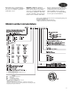
Product Data AQUAZONE™ 50P1H, P1V006-060 Single-Stage Water Source Heat Pumps with PURON® Refrigerant (R-410A) 1/ 2 to 5 Nominal Tons Single-package horizontally and vertically mounted water source heat pumps with electronic controls offer: • Non-ozone depleting Puron refrigerant (R-410A) • Three-speed PSC direct-drive, permanently lubricated fan motor (two-speed on 575-v units) • E-coated air coil available • Mute package for quieter operation available • Versatility: apply to commercial boiler/cooling
Features/Benefits (cont) Single-stage WSHP models with Puron refrigerant (R-410A) offer cooling EERs (Energy Efficiency Ratios) to 24.5 and heating COPs (Coefficiency of Performance) to 5.0. All efficiencies stated are in accordance with standard conditions under ISO (International Organization for Standardization) Standard 13256-1 and provide among the highest ratings in the industry, exceeding ASHRAE (American Society of Heating, Refrigeration and Air Conditioning Engineers) 90.1 Energy Standards.
E-coated (electro-coated) air coils The 50P1H and P1V units are available with an optional e-coated air coil. This electro-coating process will provide years of protection against corrosion from airborne chemicals. Modern building materials, such as countertops, floor coverings, paints and other materials, can “outgas” chemicals into the indoor air. Some of these chemicals are suspected of contributing to corrosion in the air coils found in both traditional and geothermal heating and cooling equipment.
Features/Benefits (cont) Accessory output — A 24-v output is provided to cycle a motorized water valve or damper actuator with compressor in applications such as variable speed pumping arrangements. Performance Monitor (PM) — This unique feature monitors water temperatures to warn when the heat pump is operating inefficiently or beyond typical operating range. Field selectable switch initiates a warning code on the unit display.
digital wall sensors communicating over Sensor Link (S-Link) communication protocol completes a system of networked control. Humidity control — Aquazone 50P1H, P1V units provide very good latent capacity and are an excellent choice for controlling humidity within a zone in many applications. The latent capacity of the units can be increased based on zone conditions with either the use of fan speed control and a humidistat.
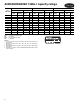
AHRI/ASHRAE/ISO 13256-1 capacity ratings WATER LOOP HEAT PUMP 50P1 UNIT SIZE COP db EER wb Cooling 86 F GROUND WATER HEAT PUMP Heating 68 F 5,800 13.2 7,500 4.7 6,900 21.1 6,200 4.0 6,200 15.4 4,900 3.4 009 8,800 13.4 11,600 4.2 10,100 21.0 9,800 3.9 9,300 15.7 7,900 3.4 012 11,700 13.5 15,200 4.3 13,700 20.8 12,500 3.8 12,000 14.9 9,900 3.2 015 14,500 15.4 17,300 5.0 16,800 24.5 14,400 4.4 15,000 17.2 11,100 3.6 018 17,300 14.3 21,500 5.
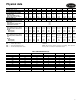
Physical data 50P1 UNIT SIZE COMPRESSOR (1 Each) FACTORY CHARGE R-410A (oz) PSC FAN MOTOR AND BLOWER (3 Speeds) Fan Motor (Hp) High Static Fan Motor (Hp) Blower Wheel Size (D x W) (in.) COAX VOLUME (gal.) WATER CONNECTION SIZE, FPT (in.) UNIT MAXIMUM WATER WORKING PRESSURE (psig)* Base Unit Internal Motorized Water Valve Internal Auto Flow Valve 50P1V UNITS Air Coil Dimensions (H x W) (in.) Throwaway Filter, Standard 1-in. Weight Operating (lb) Packaged (lb) 50P1H UNITS Air Coil Dimensions (H x W) (in.
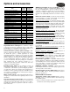
Options and accessories ITEM Aquazone™ System Control Panel 2-in.
• The 50RLP model nomenclature is used to customize the control panel options to control all WSHP system requirements. • Panel can be ordered to include 2, 4, 6, or 8 stages of system heat rejection. • Panel can be ordered to include 2, 4, 6, or 8 stages of system heat addition. • Panel can be ordered with unique WSHP zone operation capabilities for stand-alone systems (i.e., noncommunicating) to control 10 or 18 zones of WSHP units.
Options and accessories (cont) sensors (for use in demand control ventilation), and linkage thermostats (to control multiple units from one thermostat). Two-way motorized control valve can be provided for applications involving open type systems or variable speed pumping. This valve will slowly open and close in conjunction with the compressor operation to shut off or turn on water to the unit.
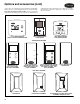
Dimensions 50P1H006-060 UNITS OVERALL CABINET (in.) 50P1H UNIT SIZE 1 Loop A B C Width Length Height 006,009, 012 22.5 40.3 ELECTRICAL KNOCKOUTS (in.) WATER CONNECTIONS (in.) D In 11.5 3 Condensate 3/4-in. FPT 2 Loop E In 3.8 1.5 Loop In/Out FPT H J K 1/2 1/ 2 3/ 4 F E Out Out AA BB 8.6 3.3 0.7 1/ 2 2.9 5.9 2 1.5 RETURN CONNECTION (in.) USING RETURN AIR OPENING (±0.10 in.) DISCHARGE CONNECTION (in.) DUCT FLANGE INSTALLED (±0.10 in.
Dimensions (cont) 50P1V006-060 UNITS OVERALL CABINET (in.) 50P1V UNIT SIZE 006,009, 012 ELECTRICAL KNOCKOUTS (in.) WATER CONNECTIONS (in.) 1 Loop A Width B Depth C Height 22.5 21.3 22.5 D In E In 3.8 1.5 3 Condensate 3/4-in. FPT 2 Loop F E Out Out 8.7 1.5 Loop In/Out FPT RETURN CONNECTION (in.) USING RETURN AIR OPENING (±0.10 in.) DISCHARGE CONNECTION (in.) DUCT FLANGE INSTALLED (±0.10 in.
Selection procedure (50P1H024 unit example) I Determine the actual cooling and heating loads at the desired dry bulb and wet bulb conditions. Given: Total Cooling (TC) . . . . . . . . . . . . . . .24,500 Btuh Sensible Cooling (SC) . . . . . . . . . . . . .21,800 Btuh Entering-Air Temperature db . . . . . . . . . . . . 80.0 F Entering-Air Temperature wb . . . . . . . . . . . . . .65 F II Determine the following design parameters from Performance Data tables.
Performance data 50P1H,P1V006 220 CFM NOMINAL AIRFLOW COOLING/220 CFM NOMINAL AIRFLOW HEATING* PRESSURE DROP EWT (F) GPM 1.5 1.5 0.8 0.8 1.1 1.1 1.5 1.5 0.8 0.8 1.1 1.1 1.5 1.5 0.8 0.8 1.1 1.1 1.5 1.5 0.8 0.8 1.1 1.1 1.5 1.5 0.8 0.8 1.1 1.1 1.5 1.5 0.8 0.8 1.1 1.1 1.5 1.5 0.8 0.8 1.1 1.1 1.5 1.5 0.8 0.8 1.1 1.1 1.5 1.5 0.8 0.8 1.1 1.1 1.5 1.5 0.8 0.8 1.1 1.1 1.5 1.5 0.8 0.8 1.1 1.1 1.5 1.
50P1H,P1V009 325 CFM NOMINAL AIRFLOW COOLING/325 CFM NOMINAL AIRFLOW HEATING* PRESSURE DROP EWT (F) GPM 2.3 2.3 1.1 1.1 1.7 1.7 2.3 2.3 1.1 1.1 1.7 1.7 2.3 2.3 1.1 1.1 1.7 1.7 2.3 2.3 1.1 1.1 1.7 1.7 2.3 2.3 1.1 1.1 1.7 1.7 2.3 2.3 1.1 1.1 1.7 1.7 2.3 2.3 1.1 1.1 1.7 1.7 2.3 2.3 1.1 1.1 1.7 1.7 2.3 2.3 1.1 1.1 1.7 1.7 2.3 2.3 1.1 1.1 1.7 1.7 2.3 2.3 1.1 1.1 1.7 1.7 2.3 2.
Performance data (cont) 50P1H,P1V012 400 CFM NOMINAL AIRFLOW COOLING/400 CFM NOMINAL AIRFLOW HEATING* PRESSURE DROP EWT (F) GPM 3.0 3.0 1.5 1.5 2.3 2.3 3.0 3.0 1.5 1.5 2.3 2.3 3.0 3.0 1.5 1.5 2.3 2.3 3.0 3.0 1.5 1.5 2.3 2.3 3.0 3.0 1.5 1.5 2.3 2.3 3.0 3.0 1.5 1.5 2.3 2.3 3.0 3.0 1.5 1.5 2.3 2.3 3.0 3.0 1.5 1.5 2.3 2.3 3.0 3.0 1.5 1.5 2.3 2.3 3.0 3.0 1.5 1.5 2.3 2.3 3.0 3.0 1.5 1.5 2.3 2.3 3.0 3.
50P1H,P1V015 525 CFM NOMINAL AIRFLOW COOLING/525 CFM NOMINAL AIRFLOW HEATING* PRESSURE DROP EWT (F) GPM 3.8 3.8 1.9 1.9 2.8 2.8 3.8 3.8 1.9 1.9 2.8 2.8 3.8 3.8 1.9 1.9 2.8 2.8 3.8 3.8 1.9 1.9 2.8 2.8 3.8 3.8 1.9 1.9 2.8 2.8 3.8 3.8 1.9 1.9 2.8 2.8 3.8 3.8 1.9 1.9 2.8 2.8 3.8 3.8 1.9 1.9 2.8 2.8 3.8 3.8 1.9 1.9 2.8 2.8 3.8 3.8 1.9 1.9 2.8 2.8 3.8 3.8 1.9 1.9 2.8 2.8 3.8 3.
Performance data (cont) 50P1H,P1V018 600 CFM NOMINAL AIRFLOW COOLING/600 CFM NOMINAL AIRFLOW HEATING* PRESSURE DROP EWT (F) GPM 4.5 4.5 2.3 2.3 3.4 3.4 4.5 4.5 2.3 2.3 3.4 3.4 4.5 4.5 2.3 2.3 3.4 3.4 4.5 4.5 2.3 2.3 3.4 3.4 4.5 4.5 2.3 2.3 3.4 3.4 4.5 4.5 2.3 2.3 3.4 3.4 4.5 4.5 2.3 2.3 3.4 3.4 4.5 4.5 2.3 2.3 3.4 3.4 4.5 4.5 2.3 2.3 3.4 3.4 4.5 4.5 2.3 2.3 3.4 3.4 4.5 4.5 2.3 2.3 3.4 3.4 4.5 4.
50P1H,P1V024 800 CFM NOMINAL AIRFLOW COOLING/800 CFM NOMINAL AIRFLOW HEATING* PRESSURE DROP EWT (F) GPM 6.0 6.0 3.0 3.0 4.5 4.5 6.0 6.0 3.0 3.0 4.5 4.5 6.0 6.0 3.0 3.0 4.5 4.5 6.0 6.0 3.0 3.0 4.5 4.5 6.0 6.0 3.0 3.0 4.5 4.5 6.0 6.0 3.0 3.0 4.5 4.5 6.0 6.0 3.0 3.0 4.5 4.5 6.0 6.0 3.0 3.0 4.5 4.5 6.0 6.0 3.0 3.0 4.5 4.5 6.0 6.0 3.0 3.0 4.5 4.5 6.0 6.0 3.0 3.0 4.5 4.5 6.0 6.
Performance data (cont) 50P1H,P1V030 1000 CFM NOMINAL AIRFLOW COOLING/1000 CFM NOMINAL AIRFLOW HEATING* PRESSURE DROP EWT (F) GPM 7.5 7.5 3.8 3.8 5.6 5.6 7.5 7.5 3.8 3.8 5.6 5.6 7.5 7.5 3.8 3.8 5.6 5.6 7.5 7.5 3.8 3.8 5.6 5.6 7.5 7.5 3.8 3.8 5.6 5.6 7.5 7.5 3.8 3.8 5.6 5.6 7.5 7.5 3.8 3.8 5.6 5.6 7.5 7.5 3.8 3.8 5.6 5.6 7.5 7.5 3.8 3.8 5.6 5.6 7.5 7.5 3.8 3.8 5.6 5.6 7.5 7.5 3.8 3.8 5.6 5.6 7.5 7.
50P1H,P1V036 1,200 CFM NOMINAL AIRFLOW COOLING/1,200 CFM NOMINAL AIRFLOW HEATING* PRESSURE DROP EWT (F) GPM 9.0 9.0 4.5 4.5 6.8 6.8 9.0 9.0 4.5 4.5 6.8 6.8 9.0 9.0 4.5 4.5 6.8 6.8 9.0 9.0 4.5 4.5 6.8 6.8 9.0 9.0 4.5 4.5 6.8 6.8 9.0 9.0 4.5 4.5 6.8 6.8 9.0 9.0 4.5 4.5 6.8 6.8 9.0 9.0 4.5 4.5 6.8 6.8 9.0 9.0 4.5 4.5 6.8 6.8 9.0 9.0 4.5 4.5 6.8 6.8 9.0 9.0 4.5 4.5 6.8 6.8 9.0 9.
Performance data (cont) 50P1H,P1V042 1,350 CFM NOMINAL AIRFLOW COOLING/1,350 CFM NOMINAL AIRFLOW HEATING* PRESSURE DROP EWT (F) GPM 10.5 10.5 5.3 5.3 7.9 7.9 10.5 10.5 5.3 5.3 7.9 7.9 10.5 10.5 5.3 5.3 7.9 7.9 10.5 10.5 5.3 5.3 7.9 7.9 10.5 10.5 5.3 5.3 7.9 7.9 10.5 10.5 5.3 5.3 7.9 7.9 10.5 10.5 5.3 5.3 7.9 7.9 10.5 10.5 5.3 5.3 7.9 7.9 10.5 10.5 5.3 5.3 7.9 7.9 10.5 10.5 5.3 5.3 7.9 7.9 10.5 10.5 5.3 5.3 7.9 7.9 10.5 10.
50P1H,P1V048 1,600 CFM NOMINAL AIRFLOW COOLING/1,600 CFM NOMINAL AIRFLOW HEATING* PRESSURE DROP EWT (F) GPM 12.0 12.0 6.0 6.0 9.0 9.0 12.0 12.0 6.0 6.0 9.0 9.0 12.0 12.0 6.0 6.0 9.0 9.0 12.0 12.0 6.0 6.0 9.0 9.0 12.0 12.0 6.0 6.0 9.0 9.0 12.0 12.0 6.0 6.0 9.0 9.0 12.0 12.0 6.0 6.0 9.0 9.0 12.0 12.0 6.0 6.0 9.0 9.0 12.0 12.0 6.0 6.0 9.0 9.0 12.0 12.0 6.0 6.0 9.0 9.0 12.0 12.0 6.0 6.0 9.0 9.0 12.0 12.
Performance data (cont) 50P1H,P1V060 2,000 CFM NOMINAL AIRFLOW COOLING/2,000 CFM NOMINAL AIRFLOW HEATING* PRESSURE DROP EWT (F) GPM 15.0 15.0 7.5 7.5 11.3 11.3 15.0 15.0 7.5 7.5 11.3 11.3 15.0 15.0 7.5 7.5 11.3 11.3 15.0 15.0 7.5 7.5 11.3 11.3 15.0 15.0 7.5 7.5 11.3 11.3 15.0 15.0 7.5 7.5 11.3 11.3 15.0 15.0 7.5 7.5 11.3 11.3 15.0 15.0 7.5 7.5 11.3 11.3 15.0 15.0 7.5 7.5 11.3 11.3 15.0 15.0 7.5 7.5 11.3 11.3 15.0 15.0 7.5 7.5 11.3 11.3 15.0 15.
ENTERING AIR CORRECTION TABLE HEATING CORRECTIONS Ent Air Heating DB (F) Capacity 45 50 55 60 65 68 70 75 80 1.0507 1.0327 1.0195 1.0102 1.0033 1.0000 0.9979 0.9928 0.9866 FULL LOAD COOLING CORRECTIONS 400 CFM PER TON Total Sensible Cooling Capacity Multipliers — Entering DB (F) Ent Air Cooling WB (F) 65 70 75 80 80.6 85 90 95 Capacity 50 0.7800 0.9778 * * * * * * * 55 0.8327 0.8966 1.0556 * * * * * * 60 0.8954 0.7505 0.9184 1.1056 * * * * * 65 0.9681 — 0.6778 0.8992 1.1213 1.1480 1.3439 * * 66.2 0.
Performance data (cont) MOTORIZED WATER VALVE CORRECTIONS UNIT SIZE 50P1 006 009 012 015 018 024 030 036 042 048 060 LEGEND MOPD — Maximum Operating Pressure Drop WPD — Waterside Pressure Drop 26 Cv MOPD 4.9 4.9 4.9 4.9 4.9 4.9 4.9 4.9 4.9 4.9 4.9 4.9 4.9 4.9 4.9 4.9 4.9 4.9 10.3 10.3 10.3 10.3 10.3 10.3 10.3 10.3 10.3 10.3 10.3 10.3 10.3 10.3 10.3 150 150 150 150 150 150 150 150 150 150 150 150 150 150 150 150 150 150 150 150 150 150 150 150 150 150 150 150 150 150 150 150 150 GPM 0.8 1.
BLOWER PERFORMANCE DATA — STANDARD UNIT 50P1 UNIT SIZE RATED AIRFLOW (cfm) MIN CFM 006 220 150 009 325 225 012 400 300 015 525 375 018 600 450 024 800 600 030 1000 750 036 1200 900 042 1350 1050 048 1600 1200 060 2000 1500 FAN SPEED HIGH MED LOW HIGH MED LOW HIGH MED LOW HIGH MED LOW HIGH MED LOW HIGH MED LOW HIGH MED LOW HIGH MED LOW HIGH MED LOW HIGH MED LOW HIGH MED LOW AIRFLOW (cfm) AT EXTERNAL STATIC PRESSURE (in. wg) 0.00 0.05 0.10 0.15 0.20 0.25 0.30 0.
Performance data (cont) BLOWER PERFORMANCE DATA HIGH-STATIC UNIT 50P1 RATED MIN UNIT AIRFLOW CFM SIZE (cfm) 015 525 018 600 024 800 030 1000 036 1200 042 1350 048 1600 060 2000 FAN SPEED HS HI 375 HS MED HS LOW HS HI 450 HS MED HS LOW HS HI 600 HS MED HS LOW HS HI 750 HS MED HS LOW HS HI 900 HS MED HS LOW HS HI 1050 HS MED HS LOW HS HI 1200 HS MED HS LOW HS HI 1500 HS MED HS LOW AIRFLOW (cfm) AT EXTERNAL STATIC PRESSURE (in. wg) 0.00 0.05 0.10 0.15 0.20 0.25 0.30 0.35 0.40 0.
Electrical data ELECTRICAL DATA — 50P1H, P1V UNITS WITH STANDARD PSC MOTOR FAN MOTOR FLA TOTAL UNIT FLA MIN CIRCUIT AMP MAX FUSE/ HACR BRKR 1 1 0.40 0.40 3.7 3.3 4.5 4.0 15 15 22.2 18.8 1 1 0.80 0.70 6.4 4.5 7.8 5.5 15 15 5.1 4.0 32.5 31.5 1 1 0.80 0.70 5.9 4.7 7.2 5.7 15 15 197/254 239/292 6.0 5.4 29.0 28.0 1 1 1.00 0.86 7.0 6.3 8.5 7.6 15 15 208/230-1-60 265-1-60 197/254 239/292 7.2 5.9 33.0 28.0 1 1 1.00 0.86 8.2 6.8 10.0 8.
Electrical data (cont) ELECTRICAL DATA — 50P1H, P1V UNITS WITH STANDARD PSC MOTOR AND INTERNAL SECONDARY PUMP (SPECIAL ORDER OPTION) Qty FAN MOTOR FLA TOTAL UNIT FLA PUMP FLA MIN CIRCUIT AMP MAX FUSE/ HACR BRKR 17.7 13.5 1 1 0.40 0.40 4.1 4.0 0.4 0.7 4.9 4.7 15 15 4.5 3.8 22.2 18.8 1 1 0.80 0.70 5.7 5.2 0.4 0.7 6.8 6.2 15 15 197/254 239/292 5.1 4.0 32.5 31.5 1 1 0.80 0.70 6.7 5.4 0.8 0.7 8.0 6.4 15 15 208/230-1-60 265-1-60 197/254 239/292 6.0 5.4 29.0 28.0 1 1 1.00 0.
ELECTRICAL DATA — 50P1H, P1V UNITS WITH HIGH-STATIC PSC MOTOR COMPRESSOR Qty FAN MOTOR FLA TOTAL UNIT FLA MIN CIRCUIT AMP MAX FUSE/ HACR 1 1 1.00 0.86 7.0 6.3 8.5 7.6 15 15 33.0 28.0 1 1 1.50 1.30 8.7 7.2 10.5 8.7 15 15 12.8 9.6 58.3 54.0 1 1 3.00 2.70 15.8 12.3 19.0 14.7 30 20 197/254 239/292 197/254 414/506 14.1 11.2 8.9 4.2 73.0 60.0 58.0 28.0 1 1 1 1 3.00 2.70 3.00 1.70 17.1 13.9 11.9 5.9 20.6 16.7 14.1 7.
Electrical data (cont) ELECTRICAL DATA — 50P1H, P1V UNITS WITH HIGH-STATIC PSC MOTOR AND INTERNAL SECONDARY PUMP (SPECIAL ORDER OPTION) Qty FAN MOTOR FLA TOTAL UNIT FLA PUMP FLA MIN CIRCUIT AMP MAX FUSE/ HACR BRKR 29.0 28.0 1 1 1.00 0.86 7.4 7.0 0.4 0.7 8.9 8.3 15 15 7.2 5.9 33.0 28.0 1 1 1.50 1.30 9.5 7.9 0.8 0.7 11.3 9.4 15 15 197/254 239/292 12.8 9.6 58.3 54.0 1 1 3.00 2.70 16.6 13.0 0.8 0.7 19.8 15.
Typical piping and wiring TYPICAL PIPING AND WIRING INSTALLATION A50-7728ef 33
Typical control wiring schematics UNITS WITH COMPLETE C CONTROLLER, SINGLE-PHASE Complete C LEGEND AL BM BMC BR CB CC CO FP1 FP2 HP HPWS JW LOC MV NEC PSC P1 RV — — — — — — — — — — — — — — — — — — Alarm Relay Contacts Blower Motor Blower Motor Contactor Blower Relay Circuit Breaker Compressor Contactor Condensate Overflow Sensor Water Coil Freeze Protection Sensor Air Coil Freeze Protection Sensor High-Pressure Switch High Pressure Water Switch Jumper Wire Loss of Charge Pressure Switch Motorized Valve
UNITS WITH COMPLETE C CONTROLLER, 208/230 V, THREE-PHASE UNITS Complete C LEGEND AL BM BMC BR CB CC CO COMPR FP1 FP2 HP HPWS JW LOC MV MVES NEC P1 RV — — — — — — — — — — — — — — — — — — — Alarm Relay Contacts Blower Motor Blower Motor Contactor Blower Relay Circuit Breaker Compressor Contactor Condensate Overflow Sensor Compressor Water Coil Freeze Protection Sensor Air Coil Freeze Protection Sensor High-Pressure Switch High Pressure Water Switch Jumper Wire Loss of Charge Pressure Switch Motorized Valv
Typical control wiring schematics (cont) UNITS WITH COMPLETE C CONTROLLER, 460 AND 575 V, THREE-PHASE UNITS Complete C LEGEND AL BM BMC BR CB CC CO COMPR FP1 FP2 HP HPWS JW LOC MV MVES NEC P1 PB RVS — — — — — — — — — — — — — — — — — — — — Alarm Relay Contacts Blower Motor Blower Motor Contactor Blower Relay Circuit Breaker Compressor Contactor Condensate Overflow Sensor Compressor Water Coil Freeze Protection Sensor Air Coil Freeze Protection Sensor High-Pressure Switch High Pressure Water Switch Jumper
UNITS WITH DELUXE D CONTROLLER, SINGLE-PHASE Deluxe D LEGEND AL BM BMC CB CC CO FP1 FP2 HP HPWS JW LOC MV MVES NEC P1 RVS TRANS TXV — — — — — — — — — — — — — — — — — — — Alarm Relay Contacts Blower Motor Blower Motor Capacitor Circuit Breaker Compressor Contactor Condensate Overflow Sensor Water Coil Freeze Protection Sensor Air Coil Freeze Protection Sensor High-Pressure Switch High Pressure Water Switch Jumper Wire Loss of Charge Pressure Switch Motorized Valve Motorized Valve End Switch National Elec
Typical control wiring schematics (cont) UNITS WITH DELUXE D CONTROLLER, 208/230 V, THREE-PHASE UNITS Deluxe D LEGEND AL BM BMC CB CC CO COMPR FP1 FP2 HP HPWS JW LOC MV MVES NEC P1 RVS TRANS TXV — — — — — — — — — — — — — — — — — — — — Alarm Relay Contacts Blower Motor Blower Motor Capacitor Circuit Breaker Compressor Contactor Condensate Overflow Sensor Compressor Water Coil Freeze Protection Sensor Air Coil Freeze Protection Sensor High-Pressure Switch High Pressure Water Switch Jumper Wire Loss of Cha
UNITS WITH DELUXE D CONTROLLER, 460 AND 575 V, THREE-PHASE UNITS Deluxe D LEGEND AL BM BMC BR CB CC CO COMPR FP1 FP2 HP HPWS JW LOC MV MVES NEC P1 PB RVS TRANS TXV — — — — — — — — — — — — — — — — — — — — — — Alarm Relay Contacts Blower Motor Blower Motor Capacitor Blower Relay Circuit Breaker Compressor Contactor Condensate Overflow Sensor Compressor Water Coil Freeze Protection Sensor Air Coil Freeze Protection Sensor High-Pressure Switch High Pressure Water Switch Jumper Wire Loss of Charge Pressure S
Typical control wiring schematics (cont) UNITS WITH COMPLETE C AND LON CONTROLLER Complete C LEGEND AL BM BMC BR CB CC CO FP1 FP2 HP HPWS JW1 LOC LON MV MVES NEC P1 RVS — — — — — — — — — — — — — — — — — — — Alarm Relay Contacts Blower Motor Blower Motor Capacitor Blower Relay Circuit Breaker Compressor Contactor Sensor, Condensate Overflow Sensor, Water Coil Freeze Protection Sensor, Air Coil Freeze Protection High-Pressure Switch High-Pressure Water Switch Clippable Field Selection Jumper Loss of Charg
UNITS WITH DELUXE D AND LON CONTROLLER Deluxe D LEGEND AL BM BMC BR CB CC CO FP1 FP2 HP HPWS JW1 LOC LON MV MVES NEC P1 RVS — — — — — — — — — — — — — — — — — — — Alarm Relay Contacts Blower Motor Blower Motor Capacitor Blower Relay Circuit Breaker Compressor Contactor Sensor, Condensate Overflow Sensor, Water Coil Freeze Protection Sensor, Air Coil Freeze Protection High-Pressure Switch High-Pressure Water Switch Clippable Field Selection Jumper Loss of Charge Pressure Switch Local Operating Network Mot
Typical control wiring schematics (cont) PREMIERLINK™ CONTROLLER APPLICATIONS WITH COMPLETE C CONTROL COMPLETE C CONTROL PREMIER LINK PWR Y HS1/EXH/RVS W CR CR O G R LEGEND CR — Control Relay LWT — Leaving Water Temperature Sensor SAT — Supply Air Temperature Sensor SPT — Space Temperature Sensor NOTE: Reversing valve is on in cooling mode.
BM BR CO LWT N.C.
BM CO FSD LWT N.C.
8 FIELD INSTALLED 8 6 J4 LSB 5 9 0 1 - MSTP Baud 6 SW3 J12 Field Installed Local Access Port 1 J1 2 3 SPT PLUS Sensor Shown J19 WHITE J13 GREEN 1 J14 J11 RED J17 7 BLACK J20 J5 1 J2 To SPT PLUS J22 10 3 2 1 + 2 1 PRIMARY NC FIRE/SMOKE DETECTOR CONTACT (FIELD-INSTALLED) - Gnd OA DAMPER (AO-2) (FIELD-INSTALLED) REMOTE OCCUPANCY/ FAN STATUS SWITCH (FIELD-INSTALLED) CONDENSATE OVERFLOW SWITCH AO1 – Aux Reheat or Cond. WTR. Loop Econ.
Application data Aquazone™ water source heat pump products are available in a flexible, efficient array of models, which can be used in all types of water loop, ground water, and ground loop type systems. Utilize Aquazone products to provide optimal energy efficient solutions and adapt to the most challenging design requirements.
Vertical ground loop — This system is used in vertical borehole applications. This design is well suited for retrofit applications when space is limited or where landscaping is already complete and minimum disruption of the site is desired. The vertical ground loop system contains a single loop of pipe inserted into a hole. The hole is back-filled and grouted after the pipe is inserted. The completed loop is concealed below ground.
Application data (cont) WATER QUALITY GUIDELINES CONDITION HX MATERIAL* CLOSED RECIRCULATING† OPEN LOOP AND RECIRCULATING WELL** Scaling Potential — Primary Measurement Above the given limits, scaling is likely to occur. Scaling indexes should be calculated using the limits below. pH/Calcium All N/A pH < 7.5 and Ca Hardness, <100 ppm Hardness Method Index Limits for Probable Scaling Situations (Operation outside these limits is not recommended.
COMPLETE C AND DELUXE D ELECTRONIC CONTROL FEATURES COMPARISON FEATURES BASIC FEATURES High and Low Refrigerant Pressure Protection Water Coil Freeze Protection True 24 VA Thermostat Signals Thermostat Inputs Compatible with Triacs Condensate Overflow Sensor Anti-Short-Cycle Time Delay Random Start Alarm (selectable dry contact or 24 VA) Water Valve Relay Water Valve Relay with Compressor Delay Emergency Shutdown Night Setback with Override Outdoor Air Damper Control COMPLETE C COMPLETE C WITH LON DELUXE
Application data (cont) Acoustical design Sound power levels represent the sound as it is produced by the source, the WSHP unit, with no regard to attenuation between the source and the space. Acoustical design goals are necessary to provide criteria for occupied spaces where people can be comfortable and communicate effectively over the background noise of the air-conditioning system and other background noise sources.
Vertical units Solenoid valves All guidelines established for horizontal units also apply for vertical units. In addition, since vertical units tend to be installed in small equipment rooms or closets, the following additional guidelines apply: 1. Mount the unit on a pad made of high-density sound absorbing material such as rubber or cork. Extend the pad beyond the WSHP unit footprint by at least 6 inches in each direction. 2.
Controls WSHP Open sequence of operation The WSHP Open multi-protocol controller will control mechanical cooling, heating and waterside economizer outputs based on its own space temperature input and set points. An optional CO2 IAQ (indoor air quality) sensor mounted in the space can maximize the occupant comfort. The WSHP Open controller has its own hardware clock that is automatically set when the heat pump software is downloaded to the board. Occupancy types are described in the scheduling section below.
Cooling — The WSHP Open controller will operate one or two stages of compression to maintain the desired cooling set point. The compressor outputs are controlled by the PI (proportional-integral) cooling loop and cooling stages capacity algorithm. They will be used to calculate the desired number of stages needed to satisfy the space by comparing the space temperature (SPT) to the appropriate cooling set point.
Controls (cont) connected to a coil on the discharge side of the unit and supplied by a boiler or a single-stage ducted electric heater in order to maintain the desired heating set point. Should the compressor capacity be insufficient or a compressor failure occurs, the auxiliary heat will be used.
to satisfy the space load conditions for more than 5 minutes, then the compressor will be started to satisfy the load. Should the SAT approach the maximum heating SAT limit, the economizer valve will modulate closed during compressor operation. Two-position water economizer control — The control has the capability to control a NO or NC, two-position water valve to control condenser water flow through a coil on the entering air side of the unit.
Guide specifications Single-Stage Water Source Heat Pumps with Puron® Refrigerant (R-410A) HVAC Guide Specifications Size Range: 5,800 to 66,600 Btuh Cooling Capacity 4,900 to 77,000 Btuh Heating Capacity Carrier Model Number: 50P1H, 50P1V Part 1 — General 1.01 SYSTEM DESCRIPTION A. Single package horizontally and vertically mounted water source heat pumps with Puron® refrigerant (R-410A) and electronic controls. B. Equipment shall be completely assembled, piped and internally wired.
4. The compressor will be mounted on computerselected vibration isolation springs to a large heavy gage compressor mounting tray plate, which is then isolated from the cabinet base with rubber grommets for maximized vibration attenuation. 5. Compressor shall be located in an insulated compartment away from airstream to minimize sound transmission. 6. Compressor shall have thermal overload protection. 7. The heat pumps shall be fabricated from heavy gage galvanized steel with powder coat paint finish.
Guide specifications (cont) thermostat must be provided to prevent over-cooling an already cold room. I. Controls and Safeties: 1. Electrical: a. A control box shall be located within the unit compressor compartment and shall contain a 50 va transformer, 24-volt activated, 2 or 3-pole compressor contactor, terminal block for thermostat wiring and solid-state controller for complete unit operation. b. Reversing valve and fan motor wiring shall be routed through this electronic controller. c.
j. Boilerless system control can switch automatically to electric heat at low loop water temperature. k. Dehumidistat input providing fan control for dehumidification operation via the IdealHumidity™ system. l. Multiple units connected to one sensor providing communication for up to 3 water source heat pumps. m. Selection of boilerless changeover temperature set point. n. Compressor relay staging for dual stage units or in master/slave applications.
Guide specifications (cont) 2. All water connections and electrical knockouts must be in the compressor compartment corner post as to not interfere with the serviceability of unit. Contractor shall be responsible for any extra costs involved in the installation of units that do not have this feature. K. Solid-State Permanent Split Capacitor (PSC) Fan Control Board: 1. Airflow selection shall be accomplished via 3 jumper switches on the PSC control board.
15. Multiple-protocol WSHP Open controller remote sensors for Aquazone flush-mount thermostats and DDC control options. Only Carrier sensors can be used with the WSHP Open controller. Sensors are available as follows: a. SPT Standard offers space temperature sensor with communication port. b. SPT Plus offers space temperature sensor with set point adjust, local override with indicating light and communication port. c.
Carrier Corporation • Syracuse, New York 13221 1110 10-10 Manufacturer reserves the right to discontinue, or change at any time, specifications or designs without notice and without incurring obligations. Section 6 Pg 64 Catalog No. 04-52500060-01 Printed in U.S.A.