® Owner's Manual Air-cooled, Prepackaged Automatic Standby Generators Models: US ASPASICCA007 ASPASICCA012 ASPASICCA015 (6 kW NG, 7 kW LP) (12 kW NG, 12 kW LP) (13 kW NG, 15 kW LP) © Not intended for use as Primary Power in place of utility or in life-support applications. DEADLY EXHAUST FUMES.
INTRODUCTION Thank you product line. air-cooled, automatically loads during for purchasing this model of the Carrier This model is a compact, high performance, engine-driven generator designed to supply electrical power to operate critical a utility power failure. This unit is factory installed in an all-weather, metal enclosure that is intended exclusively for outdoor installation. This generator will operate using either vapor withdrawn liquid propane (LP) or natural gas (NG).
Table of Contents Carrier Air-cooled 7 kW, 12 kW and 15 kW Generators Introduction ........................ Inside Front Cover Read This Manual Thoroughly .............................. Contents ................................................................ Operation and Maintenance .................................. How to Obtain Service .......................................... iFC iFC iFC IFC Section 3 - Maintenance .............................. 12 3.1 Fuses ..................................
SAFETY RULES IMPORTANT SAFETY INSTRUCTIONS Carrier Air-cooled 7 kW, 12 kW and 15 kW Generators SAVE THESE INSTRUCTIONS - The manufacturer suggests that these rules for safe operation be copied and posted near the unit's installation site. Safety should be stressed to all operators and potential operators of this equipment. GENERAL Study these SAFETY RULES carefully before installing, operating or servicing this equipment. Become familiar with this Owner's Manual and with the unit.
SAFETY RULES IMPORTANT SAFETY INSTRUCTIONS /A CarrierAir-cooled 7 kW, 12 kW and 15 kW Generators ELECTRICAL Extinguishers rated "ABC" by the National Fire Protection Association are appropriate for use on the standby electric system. Keep the extinguisher properly charged and be familiar with its use. Consult the local fire department with any questions pertaining to fire extinguishers.
o • o Section 1 -- General Information GENERAL Carrier Air-cooled 7 kW, 12 kW and 15 kW Generators NFORMATON _Only qualified electricians or contractors should attempt such installations, which must comply strictly with applicable codes, standards and regulations. 1.
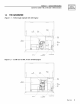
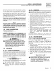
Section 1 -- General Information CarrierAir-cooled 7 kW, 12 kW and 15 kW Generators 1.4 THE GENERATOR Figure 1.1 - 7 kW, Single Cylinder GH-410 GENERAL INFORMATION Engine Conirol Oil Data Dipsiick '\, Decal \,\ , \\ ', \ , \ GFCI ........ Outlet Exhaust Enclosure Fuel -" _0 /' Figure 1.2 - 12 kW and 15 kW, V-twin C / Oil Filler " Battery / Compadrnant Fuel ..... " Inlel Composite Base GT-990 Engine Contrd Oil Dipstick Data Deaa \ \ Panel \\ \ .......
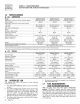
o • o Section 1 -- General Information GENERAL Carrier Air-cooled 7 kW, 12 kW and 15 kW Generators NFORMAT ON 1.5 SPECIFICATIONS 1.5.1 GENERATOR Model Rated Max. Continuous Power Capacity (Watts*) Rated Voltage Rated Max. Continuous Load Current (Amps) 120 Volts** 240 Volts Main Line Circuit Breaker Phase Number of Rotor Poles Rated AC Frequency Power Factor Recommended Air Filter Battery Requirement (At 0° F -17.
Section 1 -- General Information GENERAL INFORMATION CarrierAir-cooled 7 kW, 12 kW and 15 kW Generators Should the primary fuel need to be changed to LP gas, the fuel system needs to be reconfigured. See Section 1.9 for instructions on reconfiguration of the fuel system. Recommended fuels should have a Btu content of at least 1,000 Btus per cubic foot for natural gas; or at least 2,520 Btus per cubic foot for LP gas. Ask the fuel supplier for the Btu content of the fuel.
Section 1 -- General Information GENERAL INFORMATION Carrier Air-cooled 7 kW, 12 kW and 15 kW Generators 1.10 BATTERY INSTALLATION _A Fill the battery with the proper electrolyte fluid if necessary and have the battery fully charged before installing it. Before installing and connecting the following steps: the battery, complete 1. Set the generator's AUTO/OFF/MANUAL switch to OFF. 2. Turn off utility power supply to the transfer switch. 3. Remove the 7.
Section OPERATION 2 -- Operation Carrier Air-cooled 7 kW, 12 kW and 15 kW Generators Servicing of the battery is to be performed or supervised by personnel knowledgeable of batteries and the required precautions. Keep unauthorized personnel away from batteries. When replacing the battery, use the following type of battery: Group 26 12-volt DC, negative ground battery with a rating of 350 cold-cranking amps minimum for 7 kW; 525 cold-cranking amps minimum for 12 and 15 kW at-17.8 ° C (0 ° F) minimum.
OPERATION Section 2 -- Operation Carrier Air-cooled 7 kW, 12 kW and 15 kW Generators 2.3 AUTOMATIC TRANSFER OPERATION To select automatic operation, do the following: 1. 2. 3. Make sure the transfer switch main contacts are set to their UTILITY position, i.e., loads connected to the utility power source (Figure 2.2). Be sure that normal UTILITY power source voltage is available to transfer switch terminal lugs N1 and N2. Set the generator's AUTO/OFF/MANUAL switch to AUTO. 4.
Section 2 -- Operation OPERATION Carrier Air-cooled 7 kW, 12 kW and 15 kW Generators 2.5 MANUAL TRANSFER OPERATION 2.5.1 TRANSFER TO GENERATOR POWER SOURCE To start the generator and activate the transfer switch manually, proceed as follows: 1. 2. 3. Set the generator's to OFF. AUTO/OFF/MANUAL Use the manual transfer handle inside the transfer switch to move the main contacts to their "Standby" position, i.e., loads connected to the standby power source (Figure 2.2). 4. Figure 2.2 - Manual 1.
OPERATION Section 2 -- Operation Carrier Air-cooled 7 kW, 12 kW and 15 kW Generators NOTE: 2.7.3 The exerciser will only work in the AUTO mode and will not work unless this procedure is performed. The exerciser will need to be reset every time the 12-volt battery is disconnected and then reconnected. ;_ CAUTION _The the controller exerciser WILL NOT workboard if dip (Remote switch 2 Not on printed circuit Auto) is ON.
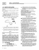
Section 3 -- Maintenance Carrier Air-cooled 7 kW, 12 kW and 15 kW Generators Figure 3.1 - Generator ' I 0UTLET FUSE z _ Control Panel POS__ iNSTALLATiON STAR.UP ADJUSTMENTS Figure 3.3 -- Oil Dipstick and Fill, 12 kW and 15 kW EX EEHNAL GFCI 0H Dipstick \ \ 75A ...... AUTO _ OFF MAN C_RGU_T BREAKER 12 VDC SYST O ii • ii SET EXERCISE TIME 3.2 ACCESSORY OUTLET 75A MAX CHECKING THE ENGINE OIL LEVEL For oil capacities, see "Specifications," Section 1.5.
Section 3 -- Maintenance MAINTENENANCE Carrier Air-cooled 7 kW, 12 kW and 15 kW Generators Figure 3.4 - Oil Drain Hose and Filter Figure 3.5 -- 7 kW, Engine Air Cleaner Location Fuel Low OHSwitch HighT_ _Switch ReguJator/ ¢ Scre_ OHFHter Figure 3.6 -- 3.4 CHANGING THE OIL FILTER 12 kW and 15 kW Engine Air Cleaner Screw Change the engine oil filter as follows: 1. 2. 3. 4. 5. 3,5 With the oil drained, remove the old oil filter by turning it counterclockwise.
Section 3 -- Maintenance Carrier Air-cooled 7 kW, 12 kW and 15 kW Generators Figure 3.7 - Setting the Spark Plug Gap SET PLUG GAP AT 0.76 mm (.030 inch) - 7 kW 0.508 mm (.020 inch) - 12 kW & 15 kW 3.7 BATTERY MAINTENANCE 1. 2. 3. Inspect the battery posts and cables for tightness and corrosion. Tighten and clean as necessary. Check the battery fluid level of unsealed batteries and, if necessary, fill with Distilled Water Only. Do not use tap water in batteries.
Section 3 -- Maintenance Carrier Air-cooled 7 kW, 12 kW and 15 kW Generators MAINTENENANCE Figure 3.8 - Coofing Vent Locations [] 5. Set the AUTO/OFF/MANUAL switch to OFF and turn off the utility power to the transfer switch. Remove the 7.5A and 15A fuses from the generator control panel. Disconnect the battery cables as outlined in "General Hazards" (page 2). Turn on the utility power supply to the transfer switch in order to power the emergency load centers circuits while utility power is available.
Section 4 -- Service Schedule SERVICE Carrier Air-cooled 7 kW, 12 kW and 15 kW Generators 4.1 SERVICE SCHEDULE ATTENTION: It is recommended that all service work be performed by the nearest Carrier Dealer. SYSTEM/COMPONENT X = Action R = Replace as Necessary * = Notify Dealer if Repair is Needed.
TROUBLESHOOTING 5.1 Section 5 - Troubleshooting Carrier Air-cooled 7 kW, 12 kW and 15 kW Generators TROUBLESHOOTING GUIDE PROBLEM CAUSE CORRECTION The engine will not crank. 1. 1. 2. 3. 4. 5. The engine cranks but will not start. The Auto/Off/Manual switch Loose, corroded or defective battery cables. Defective starter contactor. (7 kW) Defective starter motor. 2. Replace 15A fuse in generator control panel. Tighten, clean or replace as necessary. 3. 4. 5. * 1. Out of fuel. 1.
Section 6 -- Warranty CarrierAir-cooled 7 EW, 12 EW and 15 EW Generators CARRIER "TWO YEAR" LIMITED WARRANTY "PREPACKAGED EMERGENCY AUTOMATIC STANDBY FOR GENERATORS" For a period of two years from the date of original sale, warrants that its generator will be free from defects in material and workmanship for the items and period set forth below. Carrier will, at its option, repair or replace any part which, upon examination, inspection and testing by a Carrier Dealer, is found to be defective.
Section 6 - Warranty Carrier Air-cooled 7 kW, 12 kW and 15 kW Generators CALIFORNIA EMISSION CONTROL WARRANTY STATEMENT YOUR WARRANTY RIGHTS AND OBLIGATIONS The California Air Resources Board (CARB) and Generac Power Systems, Inc. (Generac) are pleased to explain the Emission Control System Warranty on your new engine.* In California, new utility, and lawn and garden equipment engines must be designed, built and equipped to meet the state's stringent anti-smog standards.
Section 6 - Warranty CarrierAir-cooled 7 EW, 12 EW and 15 EW Generators EMISSION CONTROL SYSTEM WARRANTY Emission Control System Warranty (ECS Warranty) for 1995 and later model year engines: (a) Applicability: This warranty shall apply to 1995 and later model year engines. The ECS Warranty Period shall begin on the date the new engine or equipment is purchased by/delivered to its original, end-use purchaser/owner and shall continue for 24 consecutive months thereafter.
® PART NO. 0F6902 CATALOG NO. OMASPAS07-2 REV. * (6/01/05) PRINTED IN U.S.A.