
Portable Generator User Manual

OPERATION
Section 2 -- Operation
Carrier Air-cooled 7 kW, 12 kW and 15 kW Generators
2.3 AUTOMATIC TRANSFER
OPERATION
To select automatic operation, do the following:
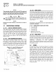
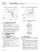
1. Make sure the transfer switch main contacts are set
to their UTILITY position, i.e., loads connected to the
utility power source (Figure 2.2).
2. Be sure that normal UTILITY power source voltage is
available to transfer switch terminal lugs N1 and N2.
3. Set the generator's AUTO/OFF/MANUAL switch to
AUTO.
4. Set the generator's main circuit breaker to its ON (or
closed) position.
With the preceding steps complete, the generator will
start automatically when utility source voltage drops
below a preset level. After the unit starts, loads are
transferred to the standby power source. Refer to Section
2.4, "Sequence of Automatic Operation."
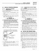
2.3.1 12 VDCACCESSORY OUTLET
Your generator is equipped with a 12 VDC accessory
outlet in the Generator Control Panel. (Figure 2.1) With
the generator running or in standby mode, this outlet may
be used to temporarily power low power accessories
such as a work light, cell phone, radio or any other
automotive style accessory. This outlet is capable of
delivering a MAXIMUM of 7.5 Amps. If the accessory to
be used through this circuit demands too much power,
the fuse that protects this circuit will melt open and the
circuit will not be functional.
WARNING
This 12 VDC outlet draws power from the
generator's starting battery and extended use
of this outlet may drain the battery and the
engine may not start. This outlet should NOT
be used for battery charging.
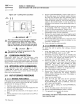
2.3.2 120 VAC GFCI OUTLET
Your generator is equipped with an external, 15 amp, 120
volt, GFCl convenience outlet that is located in the right
rear of the generator enclosure. (Figures 1.1 and 1.2,
page 5) When the generator is running, in the absence of
utility power, this outlet may be used to power items
outside your home such as lights or power tools. This
outlet may also be used when utility power is present by
running the generator in manual mode. This oultlet does
not provide power if the generator is not running. This
outlet is protected by a 15-amp circuit breaker located in
the generator control panel. (Figure 3.1).
2.4 SEQUENCE OF AUTOMATIC
OPERATION
The generator's control panel houses a control logic
circuit board. This board constantly monitors utility power
source voltage. Should that voltage drop below a preset
level, circuit board action will signal the engine to crank
and start. After the engine starts, the circuit board signals
the transfer switch to activate and connect load circuits to
the standby power supply (load terminal lugs T1/T2
connect to terminal lugs El/E2).
Upon restoration of utility power supply, generator circuit
board action signals the transfer switch to transfer loads
back to the utility power supply. After retransfer, the
engine is signalled to shut down.
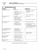
The actual sequence of operation is controlled by
sensors and timers on a control logic circuit board, as
follows:
A. Utility Voltage Dropout Sensor
• This sensor monitors utility source voltage.
• If utility source voltage drops below about 70 percent
of the nominal supply voltage, the sensor energizes
a 15-second timer.
• Once the timer has expired, the engine will crank and
start.
B. Engine Warm-up Time Delay
• This mechanism lets the engine warm up for about
10 seconds before the load is transferred to the
standby source.
C. Standby Voltage Sensor
• This sensor monitors generator AC output voltage.
When the voltage has reached 50 percent of the
nominal rated voltage, transfer to standby can occur.
D. Utility Voltage Pickup Sensor
• This sensor monitors utility power supply voltage.
When that voltage is restored above 70 percent of
the nominal source voltage, a retransfer time delay
starts timing.
E. Retransfer Time Delay
• This timer runs for about 15 seconds.
• At end of a 15-second delay, circuit board action de-
energizes transfer relay in the transfer switch.
• Retransfer to utility power source then occurs.
F. Engine Cool-down Timer
• When the load is transferred back to utility power
source, the engine cool-down timer starts timing.
• The timer will run for about one minute, and the
generator will then shut down.
10 Carrier