
Portable Generator User Manual
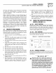

MAINTENENANCE
Section 3 -- Maintenance
Carrier Air-cooled 7 kW, 12 kW and 15 kW Generators
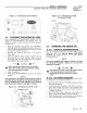
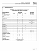
Figure 3.4 - Oil Drain Hose and Filter
Low OHSwitch HighT_ _Switch
¢
OHFHter
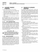
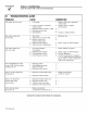
3.4 CHANGING THE OIL FILTER
Change the engine oil filter as follows:
1.
With the oil drained, remove the old oil filter by
turning it counterclockwise.
2. Apply a light coating of clean engine oil to the gasket
of the new filter. See Section 1.5.2 for recommended
filter.
3. Screw the new filter on by hand until its gasket lightly
contacts the oil filter adapter. Then, tighten the filter
an additional 3/4 to one turn (Figure 3.4).
4. Refill with the proper recommended oil (see Section
3.3.1 ). See Section 1.5.2 for oil capacities.
5. Start the engine and check for leaks.
3,5 CHANGING THE ENGINE
AIR CLEANER
3.5.1 7 KW, 12 KWAND 15 KW
GENERATORS
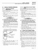
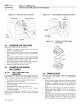
See Figures 1.1 and 1.2, for the location of the air
cleaner. Use the following procedure (Figures 3.5 & 3.6):
1. Turn the two screws counterclockwise to loosen.
2. Remove the cover and air filter.
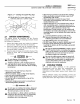
3. Wipe away dust or debris from inside of the air box
and around edges.
4. Install the new air cleaner into the air box.
5. Install the cover. Turn the two cover screws
clockwise to tighten.
See the "Service Schedule," Section 4.1, for air cleaner
maintenance. See Section 1.5.1 for air filter replacement
part number.
14 Carrier
Figure 3.5 -- 7 kW, Engine Air Cleaner Location
Scre_
Fuel
ReguJator/
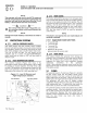
Figure 3.6 -- 12 kW and 15 kW Engine
Air Cleaner
Screw
Cover
FHter
3.6 SPARK PLUG(S)
Reset the spark plug(s) gap or replace the spark plug(s)
as necessary. See Section 4.1 for maintenance
requirements.
1. Clean the area around the base of the spark plug(s)
to keep dirt and debris out of the engine. Clean by
scraping or washing using a wire brush and
commercial solvent. Do not blast the spark plug(s) to
clean.
2. Remove the spark plug(s) and check the condition.
Replace the spark plug(s) if worn or if reuse is
questionable. See Section 4.1 for recommended
inspection.
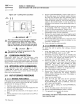
3. Check the spark plug gap using a wire feeler gauge.
Adjust the gap to 0.76 mm (0.030 inch) for 7 kW and
0.50 mm (0.020 inch) for 12 kW and 15 kW by
carefully bending the ground electrode (Figure 3.7).