CRHEATER101A00-CRHEATER112A00, CRHEATER103B00,CRHEATER104B00, CRHEATER113B00-CRHEATER116B00 CRHEATER117A00-CRHEATER119A00 CRHEATER128B00,CRHEATER129B00 CRHEATER264A00-CRHEATER269A00, CRHEATER288A00-CRHEATER299A00 CRHEATER301A00,CRHEATER308A00 CRHEATER316A00-CRHEATER322A00 CRSINGLE037A00-CRSINGLE054A00 SMALL ROOFTOP UNITS ACCESSORY ELECTRIC HEATER AND SINGLE POINT BOX ELECTRIC COOLING AND HEAT PUMP SELECT 3 to 15 TONS Installation Instructions TABLE OF CONTENTS SAFETY CONSIDERATIONS . . . . . . . . . . . .
PACKAGE USAGE CARRIER MODELS MODEL NUMBER CHASSIS GROUP UNIT SIZES 50HC AC --- 2 04-14 50HCQ HP--- 2 04-12 50KC AC --- 1 04-06 50KCQ 04-06 50LC HP--- 1 AC --- 3 50TC AC --- 1 04-16 50TCQ HP--- 1 04-14 ELECTRIC HEATERS CRHEATER288A00--296A00, 299A00, 322A00 QTY 04-12 CONTENTS 1 Heater module 1 Heater slide track 4 Screws 1 Wiring label 1 Label, Max Temp/Static CRSINGLE037A00 BRYANT MODELS MODEL NUMBER CHASSIS GROUP UNIT SIZES 547J HP-1 04-06 548J HP--- 1 04-14 549
CRSINGLE040A00 ITEM DESCRIPTION Single Point Box Housing Assembly (Height 18--- in/449 mm) CRSINGLE044A00 QUANTITY ITEM DESCRIPTION QUANTITY 1 Single Point Box Housing Assembly (Height 25--- in/639 mm) 1 Terminal block/Fuse holder 1 Terminal block 1 Fuse block 1 Fuse block 2 Fuses, 60--- A class RK5 4 Fuses, 60--- A class T (600v) 6 Power distribution harness 1 Power distribution harness 1 Conductors, Tap, #10 2 Conductors, Tap, #10 3 Rain shield with conduit seal 1 Rain shield
CRSINGLE048A00 ITEM DESCRIPTION CRSINGLE051A00 QUANTITY ITEM DESCRIPTION QUANTITY Single Point Box Housing Assembly (Height 25--- in/639 mm) 1 Single Point Box Housing Assembly (Height 33--- in/845 mm) 1 Terminal block 1 Terminal block/fuse holder 1 Fuse block 3 Fuse block 2 Fuses, 60--- A class RK5 9 Fuses, 60--- A class RK5 9 Power distribution harness 1 Power distribution harness 1 Conductors, Tap, #10 3 Conductors, Tap, #10 8 Rain shield with conduit seal 1 Terminal block
CRSINGLE054A00 ITEM DESCRIPTION QUANTITY Single Point Box Housing Assembly (Height 33--- in/845 mm) 1 Terminal block 1 Fuse block 5 Fuses, 60--- A class RK5 15 Power distribution harness 1 Conductors, Tap, #10 8 Terminal block (TB10) 2 Screws, #8 x ½--- in 2 Rain shield, small 1 Rain shield with conduit seal 1 Screws, #10 x ½--- in 8 Wire ties 7 Seal strip 1 5
GENERAL PuronR Units This installation instruction manual describes the installation of electric heaters and associated fuse block/field power termination kits (single point box or SPB) on select small rooftop units in nominal cooling capacities from 3 to 15 tons. These rooftop units use Puron refrigerant (R-410A). See Package Usage tables on page 2 for applicable unit models. Unit types include cooling units (AC) and heat pumps (HP) distributed over several chassis sizes.
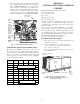
Table 1 – Heater Model Number Bare Heater Model Number C R H E A T E R 0 0 1 A 0 0 Heater Sales Package PNO Includes: Bare Heater Carton and packing materials Installation sheet C R H E A T E R 1 0 1 A or B 0 0 MODEL Carrier 50KC-A06A2A5A0A0A0 Corporation 7310 West Morris Street Indianapolis, IN 46231 U.S.A. QTY VOLTS AC PH 1 208/230 HZ RLA LRA TEST PRESSURE GAGE kg HI COMPR B LBS kg LO COMPR C LBS kg FAN MTR QTY VOLTS AC 3 60 15.6 110 REF.
MODEL 50KC-A06A2A5A0A0A0 REFRIGERANT CHARGE R410A ELECTRICAL DATA FOR ACCESSORY POWER EXHAUST ONLY ACCESSORY POWER EXHAUST MODEL NUMBER CHECK HERE VOLTS PH POWER EXHAUST HZ MIN CKT AMPS FLA FUSE OR HACR BREAKER PER NEC MAXIMUM OVERCURRENT POROTECTION DEVICE MINIMUM UNIT DISCONNECT FLA 28.
HP--1 Terminal Block TB10 (208/230--V Units) Two small terminal blocks (designated TB10) are included in these single-- point boxes used on select 208/230-- 3-- 60 units. SPB PNO CRSINGLE 043A00 045A00 049A00 051A00 053A00 054A00 TB10 is a small single--pole terminal block, 2-1/2 in. (63 mm) long with seven ¼-in. male quick-connect terminals. One or two terminal blocks are used to aid in rearranging the unit’s base cooling power circuit into two circuits, each under 60-A MOCP.
8. Note the required wire size ampacity for the field power supply conductors as marked on the unit info plate as MIN CKT AMPS for accessory heater(s) plus convenience outlet and power exhaust when provided. Select and install suitable field power conductors from external safety disconnect to unit power connection points, or confirm wiring already provided is suitable for required MIN CKT AMPS.
box which are not used must be plugged before installing the SPB. Use foil tape or reinstall the bushings from the outside of the control box prior to securing the SPB. (See Fig. 9.) 8. Remove the single point box cover. Secure single point box to the underside of the control box with the 2 screws provided. (See Fig. 3.) Re-- install bushing on the SPB tap conductors. (See Fig. 9.) 9.
In the unit control box, relocate these wires: At IFC terminal 13, disconnect Compressor 1 BLU and Compressor 2 ORN leads; reconnect at TB10A. At C1 terminal 13, disconnect ID Fan YEL lead; reconnect at TB10B. At C1 terminal 11, disconnect BLK jumper; reconnect to IFC terminal 11.
(3.) Units requiring NO TB10 terminal block Connect both sets of tap conductors to unit terminal block TB1; connect at: BLK: terminal 11 YEL: terminal 12 BLU: terminal 13 Route the first set of tap conductors (attached at upper fuse block, with bushing per Step 5) into the main control box. Route the second set of tap conductors (attached at second fuse block) into the main control box. HEATER 012A CIR#1 CIR#2 HEATER 017A C101084 Fig.
Installing Electric Heater CRHEATER101A00-109A00, 110A-112A00, 103B00, 104B00, 113B00-116B00, 117A00, 128B00, 129B00, 264A00-269A00, 297A00-299A00, 301A00, 308A00, 316A00-322A00 1. Identify heater cover(s) to remove. See Fig. 16 and 17.
Fig. 12 - Examples of slot 2 without notch and with notch 5. Single-phase heater conversion 208/230-v heaters 101A00-104B00 are factory-wired for 3-phase applications but can be converted to single-phase by changing one wire as described below. Three-phase applications: Skip to Step 6. For single-phase applications, rewire the heater as follows (see Fig. 13): a. Connect RED wire provided with kit to Heater Relay (HR) and to L1 as shown. b.
7. Factory control wiring for heaters runs from unit control box to terminal block TB-4, mounted in the heater compartment above module 1 location. (See Fig. 6 and 19-24.) Connect the heater control wiring at TB-4. BD236B N—TRAN 3O—BV2075 E 60 HZ 30-8703 30V—OR 200V—RD OV—YL D 24V 75VA C—COMM HEATER SLIDE TRACK FLANGE TRACK SCREWS KEY FOR MODULE LOCATION 1 C10557 Fig.
CONTROL BOX (REF) SCREW (2) ROUTE HEATER WIRES THROUGH GROMMET SCREW (8) GROMMET For simplicity, not all control wiring internal to the electric heaters is shown. HEATER COVER Fig. 20 - Accessory Electric Heater Control Connections (AC-1 Size 08-14, AC-2 Size 08-12) (CRHEATER128B00, 129B00 only) DISCONNECT Only CRHEATER301A00 is shown in the figure. CRHEATER128B00-129B00 has only one bank of heaters with a wide mounting plate covering both slots. C13447 Fig.
DEFROST BOARD P3-3 E-HEAT ORN P3-3 BRN TB4 ORN BRN 1 3 VIO BRN BRN VIO Field Connections Elec Htr VIO HR2 VIO HR1 BRN BRN C11554 HR1: On Heater 1 in Position #1 HR2: On Heater 2 in Position #2 (if installed) Fig. 24 - Accessory Electric Heater Control Connections (HP-2, Size 06 and 060, 575V only) C09013 Fig.
SECTION 2 INSTALLATION, LARGE CABINET SINGLE POINT BOX (NOT SHIPPED WITH UNIT) Product Groups/Sizes included in this section: AC-- 1 16 (180) AC-- 2 14 (150) AC-- 3 08-- 12 HP-- 1 14 (150) HP-- 2 12 (120) Check sales packages – Following the project drawing schedule tables or submittal documents, select the scheduled heaters and single point boxes (if used) and place at each unit. Compare the sales package number(s) for scheduled heater modules against the approved usage table on the unit’s infoplate.
conductors (pigtails) from the single point box to the unit’s power terminal block TB-1 per unit label wiring schematic and per Appendix A or B and connection figures. A representative installation of two 480V heaters and corresponding single point box is shown in Fig. 31, 32, and 33. b. CRSINGLE051A00, 053A00 and 054A00 These kits include two sets of tap conductors (blue, yellow and black pigtails) connected at fuse blocks 1 and 2.
C10174 Fig. 31 - Heater Wiring (2-pole contactor shown, has been replaced with 3-pole contactor.) C10172 Fig.
Single Point Box Power Wires C10175 Fig. 33 - Typical Control Panel Wiring Heater Slide Track Mounting Screws C10198 Fig.
Heater Mount Locations Single Element Heater Module Dual Element Heater Module C10168 Fig. 35 - Typical Heaters Table 3 – Heater Location for Vertical Return and Discharge* Table 2 – Heater Location for Horizontal Return and Discharge* Heater Heater Slot Location Heater kW Volts Left Right CRHEATERXXXX00 288A 10.0 240 - 288A 291A 16.5 240 291A - 288A + 291A 26.5 240 291A 294A 33.5 240 288A + 294A 43.5 240 291A + 294A 50.0 240 294A + 294A 67.0 240 289A 10.0 292A 16.
C14215 Fig. 36 - Restrictor Plate heater ORN control wiring to ORN on TB4 for 1st stage heating and to VIO on TB4 for 2nd stage heating. For AC units with 2 of these heater packages that have 4 control wires, connect both the ORN and VIO control wires from the heater to ORN on TB4 for 1st stage heating and connect the ORN and VIO control wires from the other heater to VIO on TB4 for 2nd stage heating. (See Fig. 42.
Table 4 – Optional Factory Installed Disconnect Amp Ratings Unit Group Unit Sizes 04-07 AC-1 08-14 16 C11127 04-06 Fig. 38 - TB4 Wiring (AC Only) AC-2 NOTE: Optional Outdoor Temperature Control at One Heater Stage – Move heater wire to this terminal and connect outdoor temperature switch between 2nd and 3rd terminals. W2 Use 07-12 14 04-06 AC-3 12 C Use R Use C10604 04-07 Fig.
12 VIO CONTROL BOARD 3 ORN CONTROL BOARD TB4 TB4 ORN U RED HCR1 BRN HCR2 BRN HC1 BRN HC2 BRN VIO 8 BRN 12 BRN CONTROL BOARD CONTROL BOARD HCR1 LS2 LS1 RED RED RED HCR2 C11135 Fig. 42 - Electric Heater Control Connections - Air Conditioner with 1 CRHEATER294A00-296A00 TRAN2 EHR RED ORN ORN TB4 HEATER 1 TB4 ORN TS BRN HC1 BRN ORN HEATER 2 (IF INSTALLED) BRN HC1 TS RED TB4 C13468 Fig.
TRAN2 RED EHR RED BRN ORN ORN TB4 1-STG HEATER ORN VIO LS HC1 ORN BRN 2-STG HEATER TB4 HCR1 BRN HCR2 BRN BRN BRN RED 2-Stage Heater TB4 RED LS1 LS2 HCR1 RED HC1 BRN HC2 BRN HCR2 C13470 Fig. 45 - Electric Heater Control Connections-Heat Pump with 1 CRHEATER288A00-293A00 Plus 1 CRHEATER294A00-296A00 (2-Stage Heater) Terminal Block 4 (TB4) Heater Cover C10173 Fig.
Heater Covers Terminal Block 4 (TB4) C10171 Fig. 47 - Heater Wiring and Covers C11512 Fig. 48 - Max. Air Temp/Max. Ext.
UNIT POWER SUPPLY WIRING – ALL UNITS NOTE: Installers of unit power supply wiring connecting to these air conditioning and heat pump units must be familiar with applicable requirements of the National Electrical Code (NFPA Standard 70), Articles 440, 430 and 424 dealing with multiple load systems incorporating refrigeration compressors, motors and electric heating equipment. Installers must also be familiar with and observe all local codes regarding unit power supply wiring.
If marked HACR value on unit dataplate is UNCHANGED from rating unit-- mounted HACR: Reconnect the factory wiring from the factory HACR at the Single Point Box’s terminal block or fuse block FU2’s line side terminals (or to main control box’s line connection lugs if no Single Point Box is installed). Remove any factory test leads connected at HACR line side terminals; discard these wires. Connect unit power supply wires to HACR line side lugs.
APPENDIX A AC--1, AC--2 COOLING APPLICATIONS SPB CRSINGLEnnnA00 04-07 036-072 037 040 Fig. 49 Fig. 50 NONE 037 038 042 043 044 045 047 049 050 051 053 054 Fig. 51 Fig. 52 Fig. 53 08 090-091 AC-1 Units 09-12 102-121 14 150 16 180 04-06 036-060 07 072 AC-2 Units 08-09 090-102 11-12 120 1-Phase (See page 14 for conversion instructions) Fig. 49 Fig. 50 3-Phase Fig. 51 Fig. 51 Fig. 52 Fig. 53 Fig. Fig. Fig. Fig. 52 54 55 56 14 150 Fig. 51 Fig. 52 Fig. 54 Fig. 52 Fig. 57 Fig. 5 Fig. Fig.
Unit Control Box C 11 IFC 13 13 Field Power Conductors HEATER Heater Wires Unit Disconnect MOCP 60-A Max Fig. 49 - AC 1-Phase Single Point Box CRSINGLE037A00 (AC-1, Sizes 04-07; AC-2, Sizes 04-06) C13477 Unit Control Box C 11 Field Power Conductors BLK 11 23 11 Tap Conductors YEL FU2 BLK + RED HTR 1 BLU + YEL FU3 BLK + RED HTR 2 BLU + YEL Heater Wires Factory wiring connects line-side of FU2 to line-side terminals on FU3. C13478 Fig.
Unit Control Box AC-1 SIZE 16 (180) AC-2 SIZE 14 (150) HP-1 SIZE 14 (150) HP-2 SIZE 12 (120) BLK BLK TB-1 11 YEL BLU BL U 12 13 BLU Unit Control Box IFTB AC-1, AC-2 HP-1, HP-2 ALL EXCEPT ABOVE C IFC 11 13 11 11 Field Power Conductors WITH VFD BLK 13 11 YEL WITHOUT VFD BLU HEATER Unit Disconnect MOCP 60-A Max Heaters that do not require a single point kit as indicated in the Product Data are standard units with contractor-provided disconnect.
Unit Control Box AC-1 SIZE 16 (180) AC-2 SIZE 14 (150) HP-1 SIZE 14 (150) HP-2 SIZE 12 (120) BLK BLK TB-1 11 YEL BLU BLU 12 13 BLU Unit Control Box IFTB AC-1, AC-2 HP-1, HP-2 ALL EXCEPT ABOVE C 11 WITH VFD IFC 11 13 11 Field Power Conductors 13 11 WITHOUT VFD Tap Conductors TB HEATER Unit Disconnect MOCP 60-A Max Heater Wires SPB 037A 042A 047A C13480 Fig.
Unit Control Box Field Tap Power Conductors C 11 IFC 13 13 !!"5"5 Field Power Conductors Tap Conductors FU2 HEATER Heater 104 #2 if used FU3 HEATER Heater 104 #1 or Heater 105 Heater Wires Factory wiring connects line-side of FU2 to line-side terminals on FU3. This wiring not illustrated for simplicity in this figure. C10486 Fig.
Fig. 55 - AC Single Point Box CRSINGLE044A00 (AC-1, Size 08) Unit Control Box C TB-10A 11 IFC TB-10B 11 13 13 FIELD POWER CONDUCTOR TAP CONDUCTORS FU2 BLU BLK YEL YEL BLK BLU HEATER 111A or 112A CIR 1 FU3 CIR 2 FU4 HEATER Factory wiring connects line-side of FU2 to line-side terminals on FU3-FU4. This wiring not illustrated for simplicity in this figure. HEATER WIRES C10491 Fig.
Unit Control Box TB-10A C TB-10B 11 IFC 11 13 13 FIELD POWER CONDUCTOR TAP CONDUCTORS BLU FU2 BLK YEL YEL BLK BLU HEATER 111A or 112A CIR 1 FU3 CIR 2 Factory wiring connects line-side of FU2 to line-side terminals on FU3. This wiring not illustrated for simplicity in this figure. HEATER WIRES ALT. TWO HEATER MODULES C10489 Fig.
Fig. 59 - AC Single Point Box CRSINGLE050A00 (AC-1, Sizes 09-16; AC-2, Sizes 08-14) Unit Control Box C TB-10A 11 IFC TB-10B 11 13 13 FIELD POWER CONDUCTOR TAP CONDUCTORS FU2 BLU BLK YEL YEL BLK BLU HEATER 111A or 112A CIR 1 FU3 CIR 2 FU4 HEATER Factory wiring connects line-side of FU2 to line-side terminals on FU3-FU4. This wiring not illustrated for simplicity in this figure. HEATER WIRES C10491 Fig.
Unit Control Box TB-10A TB-10B C 11 Field Power Conductors IFC 11 13 13 Tap Conductors BLU BLK YEL YEL BLK BLU TB FU2 FU3 CIR 1 FU4 HEATER 111A or 112A CIR 2 FU5 HEATER 117A Heater Wires Factory wiring connects line-side of TB to line-side terminals on FU2-FU5. This wiring not illustrated for simplicity in this figure. Fig.
Unit Control Box TB-10A TB-10B C 11 Field Power Conductors IFC 11 13 13 Tap Conductors BLU BLK YEL YEL BLK BLU TB FU2 FU3 CIR 1 FU4 HEATER 111A or 112A CIR 2 FU5 HEATER 117A Heater Wires Factory wiring connects line-side of TB to line-side terminals on FU2-FU5. This wiring not illustrated for simplicity in this figure. Fig.
Unit Control Box C2 TB-10 11 C1 11 13 IFC 13 13 FIELD POWER CONDUCTOR TAP CONDUCTORS FU2 HEATER 112A CIR 1 FU3 CIR 2 FU4 HEATER 117A or 110A Factory wiring connects line-side of FU2 to line-side terminals on FU3-FU4. This wiring not illustrated for simplicity in this figure. HEATER WIRES C10567 Fig.
Unit Control Box TB1 Field Power Conductors BLK BL K YEL B LU 11 11 11 12 13 BLU YEL Tap Conductors FU2 HEATER 288A,291A FU3 HEATER 294A FU4 Heater Wires Factory wiring connects line-side of FU2 to line-side terminals on FU3,4. This wiring not illustrated for simplicity in this figure. C13463 Fig.
Unit Control Box BLK YEL BLU 11 11 11 12 13 TB1 Tap Conductors BLK Field Power Conductors YEL BLU TB FU2 HEATER 294A CIR 1 FU3 CIR 2 FU4 HEATER 294A CIR 1 FU5 CIR 2 Heater 14 Wires Factory wiring connects load-side of TB to line-side terminals on FU2-5. This wiring not illustrated for simplicity in this figure. C13464 Fig.
Unit Control Box TB-1OA C 11 TB-1OB !!13 !! IFC 11 13 Tap Conductors Field Power Conductors BLU BLK YEL YEL BLK BLU TB FU2 FU3 FU4 CIR 1 FU5 HEATER 112A CIR 2 FU6 HEATER 117A Heater Wires Factory wiring connects line-side of TB to line-side terminals on FU2-FU6. This wiring not illustrated for simplicity in this figure. Fig.
Unit Control Box TB-10 C2 11 C1 IFC 13 11 13 13 TAP CONDUCTORS FIELD POWER CONDUCTOR BLK YEL BLU BLK YEL BLU TB FU2 FU3 HEATER 117A or 110A (when used) FU4 HEATER 112A CIR 1 FU5 CIR 2 HEATER WIRES Factory wiring connects line-side of TB to line-side terminals on FU2-FU5. This wiring not illustrated for simplicity in this figure. Fig.
Unit Control Box TB1 11 FIELD POWER CONDUCTOR 12 13 TAP CONDUCTORS BLK YEL BLU TB FU2 FU3 FU4 HEATER 288A or 291A FU5 CIR 1 HEATER 294A FU6 CIR 2 14 Factory wiring connects line-side of TB to line-side terminals on FU2-FU6. This wiring not illustrated for simplicity in this figure. HEATER WIRES Fig.
APPENDIX B AC--3 50LC COOLING APPLICATIONS SPB CRSINGLEnnnA00 50LC Unit Sizes 07 04-06 NONE 037 038 047 049 050 051 08-12 Fig. 70 Fig. 71 Fig. 72 Fig. 73 Fig. 74, Fig. 75 Fig. 76 Fig. 77 Fig. 79, Fig. 80 Fig. 78 C13450 Fig. 70 - AC-3 No Single Point Box Unit Control Box BLK IFTB Field Power Conductors BLU C 11 13 11 13 Tap Conductors YEL BLK BLU HEATER #1 TB Unit Disconnect MOCP 60-A Max BLK HEATER #2 IF USED YEL BLU HEATER WIRES 50LC 004-006 SPB 037A C13461 Fig.
Unit Control Box Field Tap Power Conductors BLK BLU C 11 13 11 IFTB Tap Conductors TBF FIELD POWER CONNECTIONS BLK BLU YEL HEATER Heater 104 #2 if used FB1 HEATER Heater 104 #1 or Heater 105 Heater Wires Factory wiring connects line-side of TBF to line-side terminals on FB. This wiring not illustrated for simplicity in this figure. C13451 Fig.
Unit Control Box BLK TB3 11 YEL B LU 11 11 12 13 Field Power Conductors Tap Conductors BLK TBF HEATER 317A FB1 Heater Wires Factory wiring connects line-side of TB to line-side terminals on FB. This wiring not illustrated for simplicity in this figure. C13453 Fig.
Unit Control Box BLK TB3 11 YEL B LU 11 11 12 13 Field Power Conductors Tap Conductors BLK HEATER 318A TBF CIR 1 FB1 CIR 2 Heater Wires Factory wiring connects line-side of TB to line-side terminals on FB. This wiring not illustrated for simplicity in this figure. C13454 Fig.
Unit Control Box BLK TB1 11 YEL BL U 11 11 12 13 Field Power Conductors Tap Conductors BLK TBF HEATER #1 HEATER CIR 1 FB1 HEATER #2 IF USED CIR2 HEATER WIRES Factory wiring connects line-side of TB to line-side terminals on FB. This wiring not illustrated for simplicity in this figure. C13457 Fig.
Unit Control Box BLK TB1 11 YEL BLU 11 11 12 13 Field Power Conductors Tap Conductors TB FU2 HEATER 295A BLK YEL CIR #1 FU3 CIR #2 HEATER WIRES Factory wiring connects line-side of TB to line-side terminals on FU2 and FU3. This wiring not illustrated for simplicity in this figure. C13459 Fig.
Unit Control Box BLK TB1 11 YEL BL U 11 11 12 13 Field Power Conductors Tap Conductors TB FU2 HEATER #1 BLK YEL FU3 HEATER 295A BLK CIR #1 YEL BLU CIR #2 Factory wiring connects line-side of TB to line-side terminals on FU2 and FU3. This wiring not illustrated for simplicity in this figure. HEATER WIRES C13460 Fig.
APPENDIX C HP-1, HP-2 HEAT PUMP APPLICATIONS SPB CRSINGLEnnnA00 04-07 036-072 040 041 Fig. 81 Fig. 82 None 037 038 039 042 043 045 047 049 050 051 052 053 054 Fig. 51* Fig. 52* Fig. 83 Fig. 84 HP-1 Units 08-09 12 090-102 120 14 150 04-06 036-060 07 072 HP-2 Units 08-09 090-102 12 120 1- Phase (See page 14 for conversion instructions) 3-Phase Fig. 51* Fig. 52* Fig. 83 Fig. 84 Fig. 83 Fig. 84 Fig. 83 Fig. 84 Fig. 52* Fig. 85 Fig. 52* Fig. 86 Fig. Fig. Fig. Fig. Fig. Fig. Fig. Fig.
Unit Control Box C 11 23 11 11 Field Power Conductors Tap Conductors YEL BLK FU2 BLK + RED HTR 1 BLU + YEL FU3 BLK + RED HTR 2 BLU + YEL Heater Wires Factory wiring connects line-side of FU2 to line-side terminals on FU3. C13482 Fig. 82 - Heat Pump 1-Phase Single Point Box CRSINGLE041A00 (HP-1, Sizes 04-07) Unit Control Box C 11 IFC 11 !!137!! 13 Field Power Conductors Tap Conductors BLK FU2 YEL BLU FU3 HTR Factory wiring connects line-side of FU2 to line-side terminals on FU3.
Unit Control Box C IFC !!13 !! 11 11 13 Field Power Conductors Tap Conductors BLK FU2 YEL BLU FU3 HTR 1 FU4 HTR 2 Factory wiring connects line-side of FU2 to line-side terminals on FU3-FU4. This wiring not illustrated for simplicity in this figure. Heater Wires C10498 Fig.
Unit Control Box C2 11 C1 TB-10 11 13 IFC 13 13 FIELD POWER CONDUCTOR TAP CONDUCTORS BLK YEL BLU BLK YEL BLU FU2 FU3 HEATER 117A OR 110A Factory wiring connects line-side of FU2 to line-side terminals on FU3. This wiring not illustrated for simplicity in this figure. HEATER WIRES C10568 Fig.
Unit Control Box TB1 11 12 13 FIELD POWER CONDUCTOR TAP CONDUCTORS TB BLK YEL BLU FU2 HEATER CIR 1 FU3 CIR 2 Factory wiring connects line-side of TB to line-side terminals on FU2-FU3. This wiring not illustrated for simplicity in this figure. HEATER WIRES HEATER 6 WIRES NOTE: ALL HEATERS CONNECT TO FU3 C10569 Fig.
Unit Control Box C2 11 TB-10 C1 13 IFC 13 11 13 FIELD POWER CONDUCTOR TAP CONDUCTORS BLK YEL BLU BLK YEL BLU FU2 FU3 HEATER 112A CIR 1 FU4 HEATER 117A or 110A CIR 2 Factory wiring connects line-side of FU2 to line-side terminals on FU3-FU4. This wiring not illustrated for simplicity in this figure. HEATER WIRES C10570 Fig.
Fig.
Unit Control Box TB1 11 12 13 FIELD POWER CONDUCTOR TAP CONDUCTORS TB BLK YEL BLU FU2 FU3 CIR 1 FU4 CIR 2 Factory wiring connects line-side of TB to line-side terminals on FU2-FU4. This wiring not illustrated for simplicity in this figure. There are many heater combinations: 289A + 295A, 290A + 296A, 292A + 295A, 293A + 296A. Fig.
Unit Control Box TB-10A TB-10B C 11 Field Power Conductors IFC 11 13 13 Tap Conductors BLU BLK YEL YEL BLK BLU TB FU2 FU3 CIR 1 FU4 HEATER 112A CIR 2 FU5 HEATER 117A Heater Wires Factory wiring connects line-side of TB to line-side terminals on FU2-FU5. This wiring not illustrated for simplicity in this figure. C10505 Fig.
Unit Control Box TB-10 C2 11 C1 IFC 13 11 13 13 TAP CONDUCTORS FIELD POWER CONDUCTOR BLK YEL BLU BLK YEL BLU TB FU2 FU3 HEATER 117A or 110A (when used) FU4 HEATER 112A CIR 1 FU5 CIR 2 HEATER WIRES Factory wiring connects line-side of TB to line-side terminals on FU2-FU5. This wiring not illustrated for simplicity in this figure. Fig.
TB1 Unit Control Box 11 12 13 FIELD POWER CONDUCTOR TAP CONDUCTORS BLK YEL BLU TB FU2 FU3 FU4 HEATER 288A CIR 1 HEATER 294A FU5 HEATER 291A CIR 2 14 14 HEATER WIRES Factory wiring connects line-side of TB to line-side terminals on FU2-FU5. This wiring not illustrated for simplicity in this figure. Fig.
Unit Control Box TB-1OA C 11 TB-1OB !!13 !! IFC 11 13 Tap Conductors Field Power Conductors BLU BLK YEL YEL BLK BLU TB FU2 FU3 FU4 CIR 1 FU5 HEATER 112A CIR 2 FU6 HEATER 117A Heater Wires Factory wiring connects line-side of TB to line-side terminals on FU2-FU6. This wiring not illustrated for simplicity in this figure. Fig.
Unit Control Box $& C2 $& 11 TB-10 C1 11 13 IFC 139 13 FIELD POWER CONDUCTOR TAP CONDUCTORS TB BLK YEL BLU BLK YEL BLU FU2 FU3 FU4 CIR 1 FU5 HEATER 112A CIR 2 FU6 HEATER 117A or 110A Heater Conductors Factory wiring connects line-side of TB to line-side terminals on FU2-FU6. This wiring not illustrated for simplicity in this figure. Fig.
Unit Control Box TB1 11 FIELD POWER CONDUCTOR 12 13 TAP CONDUCTORS BLK YEL BLU TB FU2 FU3 FU4 HEATER 288A or 291A FU5 CIR 1 HEATER 294A FU6 CIR 2 14 Factory wiring connects line-side of TB to line-side terminals on FU2-FU6. This wiring not illustrated for simplicity in this figure. HEATER WIRES Fig.
Unit Control Box C IFC C 11 11 11 Field Power Conductors 13 B LK Tap Conductors B LU BLK + RED TB HEATER YEL + BLU Unit Disconnect MOCP 60-A Max BLK + RED YEL + BLU SPB 037A HEATER #2 IF USED Heater Wires C13471 Fig.
13 13 Unit Control Box BLK TB1 11 YEL BL U 11 11 12 13 Field Power Conductors Tap Conductors BLK FU2 HEATER CIR 1 HTR 294A FU3 HEATER 291A CIR 2 HEATER WIRES Factory wiring connects line-side of FU2 to line-side terminals on FU3 FU3. This wiring not illustrated for simplicity in this figure. C13473 Fig.
Unit Control Box TB1 Field Power Conductors BLK YEL BLU 11 11 11 12 13 Tap Conductors BLK FU2 HEATER HEATER 288A,291A FU3 HEATER 294A FU4 Heater Wires Factory wiring connects line-side of FU2 to line-side terminals on FU3,4. This wiring not illustrated for simplicity in this figure. C13474 Fig.
13 Unit Control Box C 11 IFC 11 13 11 13 11 Field Power Conductors Tap Conductors FU2 FU3 HEATER BLK + RED YEL + BLU SPB 040A Heater Wires Factory wiring connects line-side of FU2 to line-side terminals on FU3. FU3 This wiring not illustrated for simplicity in this figure. C13476 Fig.
24.0/32.0 16.5 27.8 13.9 7.8/10.4 013B 014B 015B 016B 017A 018A 019A 128B 129B 113B 114B 115B 116B 117A 118A 119A 128B 129B 480 600 208/240 480 208/240 50.0 41.7 36.0 18.0 33.0 18.6/24.8 12.0/16.0 14.0 012A 11.5 112A 480 8.8 011A 007A 107A 6.0 111A 006A 106A 12.1/16.0 010A 005A 105A 7.9/10.5 6.5/8.7 110A 004B 104B 208/240 109A 003B 103B 4.9/6.5 009A 002A 102A 3.3/4.
HEATER MODEL NBR 264A 265A 266A 267A 268A 269A 288A 289A 290A 291A 292A 293A 294A 295A 296A 297A 298A 299A 301A SALES PKG NBR 264A 265A 266A 267A 268A 269A 288A 289A 290A 291A 292A 293A 294A 295A 296A 297A 298A 299A 301A 600 600 600 480 208/240 600 480 208/240 600 480 208/240 480 480 208/240 VOLTS 23.0 28.0 15,0 10.0 33.5 33.5 25.2/33.5 16.5 16.5 12.4/16.5 10 10 7.5/10 25.5 23.0 14.0 11.5 6 4.9/6.
308A 316A 317A 318A 319A 320A 321A 322A 308A 316A 317A 318A 319A 320A 321A 322A CRHEATERXXXX00 HEATER MODEL NBR SALES PKG NBR 600 480 208/240 208/240 600 VOLTS 28.0 25.5 14.0 6.0 18.8/24.8 12.0/16.0 4.9/6.5 18.0 KW FLA 1-PH 26.9 30.1 16.8 7.2 52.1/60.1 33.4/38.5 13.6/15.6 17.3 FLA 3-PH 1 1 1 1 2 1 1 1 QTY CIRS Used on AC-1 APPENDIX D (CONT.
Copyright 2017 CAC / BDP D 7310 W. Morris St. D Indianapolis, IN 46231 Edition Date: 2/17 Manufacturer reserves the right to change, at any time, specifications and designs without notice and without obligations.