
Install Instructions


10
8. Note the required wire size ampacity for the field
power supply conductors as marked on the unit info
plate as MIN CKT AMPS for accessory heater(s)
plus convenience outlet and power exhaust when
provided. Select and install suitable field power
conductors from external safety disconnect to unit
power connection points, or confirm wiring already
provided is suitable for required MIN CKT AMPS.
A
L
LIED
P
A
M
O
DE
L
N
O
.
E
R
I
A
L
N
O.
C
O
RP
.
11
13
21
23
O
D
2
2
.
2
3
1
2
3
ISTED
AI
R
NDITIONING
UIP
ACCESS
346
N
.
P
/
N
2
-
56
10
-
4
RE
V
1
1
13
2
1
2
3
CONTROL
BOX
BUSHING
SINGLE
POINT BOX
MOUNTING
SCREWS
FOAM
BUSHING
DRIP BOOT
BRACKET
MOUNTING
SCREWS
HEATER
RELAYS
POWER
WIRES
HEATER
MOUNTING
SCREWS
MANUAL RESET
LIMIT SWITCH
C13467
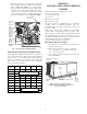
Fig. 3 - Typical Single Point Kit Installation
UNIT SPECIFIC INSTALLATION INSTRUCTIONS
The unit-specific installation instructions are presented in
two sections, grouped by common chassis and control box
design. Section 1 covers smaller chassis models and starts
on page 10. Section 2 covers the large chassis models and
starts on page 18. See table below for section assignment
for specific unit types and sizes.
Unit
Size
Group
AC--1
AC--2 AC--3 HP--1 HP--2
04, 036
05, 048
06, 060
07, 072
08, 090
09, 102
11
12, 120
14, 150
16, 180
SECTION 1
INSTALLATION, SMALL-MEDIUM
CABINET
Product Groups/Sizes included in this section:
AC--1 04--14 (036--150)
AC--2 04--12 (036--120)
AC--3 04--07
HP--1 04--12 (036--120)
HP-2 04-09 (036-102)
Check sales packages – Following the project drawing
schedule tables or submittal documents, select the
scheduled heaters and single point boxes (if used) and
place at each unit.
Compare the sales package number(s) for scheduled
heater modules against the approved usage table on the
unit’s info plate. See Fig. 1 and 2 for typical plate data. If
the scheduled heater usage does not appear on the unit
info plate label, STOP. Contact the project engineer or the
local distributor sales office for clarification.
Open the cartons and inspect for damage.
Disconnect field power supply
1.
Disconnect power to the unit. Lock-out/tag-out on
unit disconnect switch.
2.
Remove the outdoor access panel, control box
cover, and indoor access panels from the unit.
Save screws. See Fig. 4-6.
3. Use a voltmeter to check that no power is present at
unit terminal block.
DISCONNECT MOUNTING
LOCATION
UNIT BLOCK-OFF
PANEL
OUTDOOR
ACCESS PANEL
INDOOR
ACCESS
PANEL
MAX. TEMP/
STATIC LABEL
C11510
Fig. 4 - Typical Access Panel Location
(AC-1/HP-1 04-07/036-072, HP-2 04-06/036-060,
AC-2,3 04-06/036-060)
SECTION 1 UNITS
SECTION 2 UNITS