
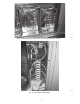
Install Instructions

25
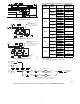
C11127
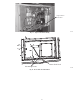
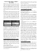
Fig. 38 - TB4 Wiring (AC Only)
NOTE:
Optional Outdoor Temperature Control
at One Heater Stage –
Move heater wire to this terminal and
connect outdoor temperature switch
between 2nd and 3rd terminals.
W2 Use
R Use
C Use
C10604
Fig. 39 - TB4 Terminal Use (HP Only)
NOTE:
Optional Outdoor Temperature Control
at One Heater Stage –
Move heater wire to this terminal and
connect outdoor temperature switch
between 2nd and 3rd terminals.
W1 Use
R Use
C Use
12
CONTROL
BOARD
8
CONTROL
BOARD
VIO
VIO
W2 Use
C11129
Fig. 40 - TB4 Terminal Use (AC Only)
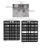
Table 4 – Optional Factory Installed Disconnect Amp Ratings
Unit
Group
Unit
Sizes
Volts
Disconnect
Size Amps
AC-1
04-07
208/230 80
460, 575 60
08-14
208/230
80
460, 575
16
208/230 115 #
460, 575 100
AC-2
04-06
208/230 80
460, 575 60
07-12
208/230
80
460, 575
14
208/230 115 #
460, 575 100
AC-3
04-06
208/230
80
460, 575
07-09
208/230
80
460, 575
12
208/230 115 #
460, 575 100
HP-1
04-07
208/230 80
460, 575 60
08-12
208/230
80
460, 575
14
208/230 115 #
460, 575 100
HP-2
04-06
208/230
80
460, 575
08-09
208/230
80
460, 575
12
208/230 115 #
460, 575 100
1---Standard Efficiency
2--- High Efficiency
3--- Ultra High Efficiency
#115 ---A is Application Limit based on factory wire size.
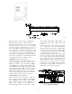
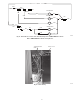
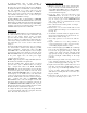
HC1
HC1
HEATER 1
*HEATER 2 (IF INSTALLED)
BRN
BRN
BRN
TB4
TB4
ORN
ORN
RED
8
12
CONTROL
BOARD
U
VIO
CONTROL
BOARD
CONTROL
BOARD
3
CONTROL
BOARD
2
* 2 stage heat shown. Connect orange wire from
Heater 2 HC1 to orange on TB4 for 1 stage heat.
LS1
ORN
LS1
LS2
ORNORN
ORN
LS1
ORN
LS1
LS2
ORNORN
ORN
C11134
Fig. 41 - Electric Heater Control Connections - Air Conditioner with 1 or 2 CRHEATER288A00-293A00