
Install Instructions

29
UNIT POWER SUPPLY WIRING –
ALL UNITS
NOTE: Installers of unit power supply wiring connecting
to these air conditioning and heat pump units must be
familiar with applicable requirements of the National
Electrical Code (NFPA Standard 70), Articles 440, 430
and 424 dealing with multiple load systems incorporating
refrigeration compressors, motors and electric heating
equipment. Installers must also be familiar with and
observe all local codes regarding unit power supply
wiring.
In most instances, adding electric heaters to these units
will result in an increase in unit power supply wire size
compared to base unit electrical loads. These changes may
also impact the size selection of the branch circuit
overload protection device and the unit safety disconnect
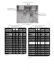
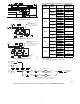
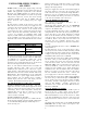
switch. Check the unit’s informative data label (see Fig.
1 and 2 for examples) for minimum wiring sizing
ampacity for full combined load (including power exhaust
if also installed), for branch circuit protection size (a
maximum value) and for unit minimum disconnect switch
size.
Device
Infopl ate Designation
Power Supply Wire MIN CKT AMPS
Branch Circuit
Protection
FUSE OR HACR
BREAKER
Disconnect Switch
MINIMUM UNIT
DISCONNECT
All wiring that terminates at a unit-mounted terminal must
be selected from wiring materials under the NEC Table
310.15(B)(16), 75 C (or higher) column only. Check
specifications for external disconnect lug sizes to
determine if 60 C wiring materials may be used between
branch circuit origin and the disconnect switch.
There are four different situations that an installer can
encounter with these units. Three are for new unit
installations (base unit has not been connected to a power
supply already): Unit without factory disconnect switch,
unit with factory disconnect switch and unit with factory
HACR breaker. The fourth situation is for an existing unit
already connected to a power supply and the heaters are
being retrofitted. For each situation, there is usually a
without single point box and a with single point box
condition. Each situation is discussed below.
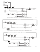
New Unit Without Factory Disconnect or HACR
Installation WITHOUT Single Point Box: Unit power
supply wires from the external (field-supplied) disconnect
switch are connected to the base unit’s power connection
terminal lugs. Refer to unit wiring label to identify these
terminals (these may be lugs on contactors or at power
terminal block). The heater power wires are also
connected at these terminals.
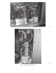
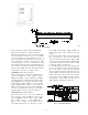
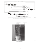
Installation WITH Single Point Box:
Remove knockouts for appropriate size conduit from unit
block-off panel and single point box. Install conduit (rigid
or electrometallic tubing) through conduit drip boot as
shown. (See Fig. 15.)
Drip boot
will accept conduit sizes 3/4-in. to 1-1/2 inches.
The drip boot eliminates the need for watertight conduit
fittings at the single point box.
Unit power supply wires from the external (field-supplied)
disconnect switch are connected to the power lugs on the
field connection device provided in the Single Point Box.
This device may be a terminal block or fuse block FU2’s
line side terminals. The heater power wires are connected
to the load side terminals on the same device.
New Unit With Factory Disconnect
The optional factory-supplied disconnect has a
maximum rating per Table 4.
Check this unit’s infodata plate for the MINIMUM
DISCONNECT SWITCH value (see Fig. 1 and 2) and
compare to the Table 4 value.
If required minimum disconnect value is LOWER than
rating in Table 4: Reconnect the factory wiring from the
factory disconnect at the Single Point Box’s terminal
block or fuse block FU2’s line side terminals (or to main
control box’s line connection lugs if no Single Point Box
is installed). Remove any factory test leads connected at
disconnect line side terminals; discard these wires.
Connect unit power supply wires to disconnect switch line
side lugs.
If required minimum disconnect value is HIGHER than
rating in Table 4:
For unit with 60--A, 80--A or 100--A disconnect, remove
the factory disconnect switch assembly and wiring. Install
a field--supplied disconnect switch sized per unit marking.
Complete connections per instructions above under “New
Unit Without Factory Disconnect or HACR.”
For unit with 115--A disconnect AND required minimum
disconnect value per unit infodata plate is less than
200--A: Remove the factory wires at load side terminals
of the disconnect switch. Size new wires based on unit
MIN CKT AMPS value for unit plus heaters plus power
exhaust (if installed). Connect new wires at disconnect
switch load side terminals and to Single Point Box’s
terminal block or fuse block FU2’s line side terminals.
Remove any factory test leads connected at disconnect
line side terminals; discard these wires. Connect unit
power supply wires to disconnect switch line side lugs.
For unit with 115--A disconnect AND required minimum
disconnect value per unit infodata plate is GREATER than
200--A: Remove the factory disconnect switch assembly
and wiring. Install a field--supplied disconnect switch
sized per unit marking. Complete connections per
instructions above under “New Unit Without Factory
Disconnect or HACR.”
New Unit With Factory HACR
The amp rating of the HACR factory installed option is
based on the size, voltage, indoor motor and other
electrical options of the unit as shipped from the factory.
When field installed accessory electric heaters are added
to the unit, the HACR may no longer be of the proper amp
rating and therefore will need to be removed from the
unit.
Check this unit’s infodata plate for the FUSE OR HACR
BREAKER value (see Fig. 1 and 2) and compare to the
factory HACR breaker rating value.