
Install Instructions

30
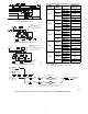
If marked HACR value on unit dataplate is
UNCHANGED from rating unit--mounted HACR:
Reconnect the factory wiring from the factory HACR at
the Single Point Box’s terminal block or fuse block FU2’s
line side terminals (or to main control box’s line
connection lugs if no Single Point Box is installed).
Remove any factory test leads connected at HACR line
side terminals; discard these wires. Connect unit power
supply wires to HACR line side lugs.
If marked HACR value on unit dataplate is GREATER
than rating on unit-mounted HACR: Remove the factory
HACR switch assembly and wiring. Install a field-supplied
fused or HACR disconnect switch sized per unit marking.
Complete connections per instructions above under “New
Unit Without Factory Disconnect or HACR.”
Existing Unit
An existing unit will usually have been installed following
the values marked on the base unit’s informative data
plate for wire sizing, branch circuit over-current
protection and disconnect switch rating. When electric
heaters are added to air conditioning (cooling) units, these
values may be changed; when electric heaters are added to
heat pump units, one or more of these values will be
changed.
Check the installed unit’s field power wires for conductor
size and determine conductor rated ampacity per NEC
Table 310.15(B)(16). Compare this value to the MIN
CKT AMPS value on the unit infoplate for base unit plus
electric heaters (plus power exhaust if connected). If the
MIN CKT AMPS value is greater than the rated ampacity
of the power supply wires, the unit power supply
conductors must be replaced.
NOTE: Supply wiring must comply with NEC (National
Electrical Code) and all local requirements.
Check the installed unit’s branch circuit over-current
protection device (fuse or HACR breaker) for rating in
amps. Compare this value to the FUSE OR HACR
BREAKER value on the unit infoplate for base unit plus
electric heaters (plus power exhaust if connected). If the
FUSE OR HACR BREAKER value is greater than the
rated ampacity of the installed device, the unit branch
circuit over-current protection device must be replaced.
Check the installed unit’s disconnect switch for rating in
amps. Compare this value to MINIMUM UNIT
DISCONNECT value on the unit infoplate for base unit
plus electric heaters (plus power exhaust if connected). If
the MINIMUM UNIT DISCONNECT value is greater
than the rated ampacity of the installed disconnect switch,
the unit disconnect switch must be replaced.
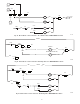
To complete the unit power wiring at the Single Point Box
or base unit terminals, follow the appropriate directions
under ”New Unit” discussions above.
Complete Unit Installation
1.
Mark the appropriate block on the unit nameplate
for the accessory heater kW installed. Note the re-
quired MIN CKT AMPS value for this unit-heater
combination. Ensure the field power conductors are
sized to handle this ampacity.
2.
Locate the heater covers. For all heaters except
CRHEATER301A00, the heater cover is the plate
removed from the heater mounting bracket in Step 4
page 11 or Step 3 page 19. For CRHEATER301A00
only, a new, wider cover is included in the accessory
heater package. See Fig. 18.
3.
Place adhesive-backed wiring label on flanged
side of heater cover.
4.
Fasten heater cover to heater module with 2 screws
provided with heater. Flanges of cover must face out.
(See Fig. 47.)
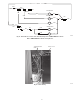
5. Set manual reset limit switch (on supply fan hous-
ing) by depressing button located between the ter-
minals on the switch. (See Fig. 3.)
6. Close single point box cover and secure with one
screw.
7. Replace control box cover, using remainder of
screws saved from page 11, Step 4 or page 18, Step
3 of Installing Single Point Box sections.
8.
Run conduit through (rigid or EMT) the conduit drip
boot in the rain shield bracket to the single point
box. Provide an appropriate fitting to connect the
conduit to the single point box wall and ground
appropriately. (See Fig. 31.) Drip boot eliminates the
need for watertight conduit fittings at the single
point box.
9.
Run wire through conduit connecting outside power
to the designated terminals at the top of the single
point box. Ground appropriately. (See Fig. 33.)
10.
Replace indoor and outdoor panels with screws saved
from Step 2 of Disconnect Field Supply section on
page 10 and step 3 of Install Single Point Box section
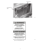
on page 19. Place adhesive-backed Max. Air/Max.
Static label on external panel that covers heaters. (See
Fig. 4, 5, and 48.)
11.
If all other work on the unit is done, reapply unit
power per lock-out/tag-out procedures.