
Install Instructions


6
GENERAL
PuronR Units
This installation instruction manual describes the
installation of electric heaters and associated fuse
block/field power termination kits (single point box or
SPB) on select small rooftop units in nominal cooling
capacities from 3 to 15 tons. These rooftop units use
Puron refrigerant (R-410A). See Package Usage tables on
page 2 for applicable unit models. Unit types include
cooling units (AC) and heat pumps (HP) distributed over
several chassis sizes. Unit types AC--1, AC--2, HP--1,
HP--2 are identified. Unit type AC--3 consists of a single
model — Carrier 50LC.
This information does not include selection data. Refer to
project plans, job submittals and selection programs for
heater and field power termination/SPB kit usage.
Some electric heaters used on these Puron (R-410A) units
may also be installed in earlier R-22 rooftop units. Refer
to Form 50-8SI or IIK-548-36-49 for installation
instructions on heater packages CRHEATER101A00
through 119A00 with earlier models. Contact your local
distributor office for a copy of this form.
Electric Heaters
Heaters are shipped with one heater per carton. The carton is
marked with a Sales Package Number. On all heaters except
CRHEATER101A00 through 119A00, 103B00, 104B00,
113B00 through 116B00, 128B00, and 129B00, the heater Model
Number (as marked on the heater infoplate) is the same as the
Sales Package number. On CRHEATER101A00 through
119A00, 103B00, 104B00, 113B00 through 116B00, 128B00,
and 129B00, the value in position 9 of the part number differs
between the sales package part number (value is 1 and bare heater
model number (value is 0). (See Table 1.)
The heaters are modular in design, with heater frames
holding open coil resistance wires strung through ceramic
insulators, limit switches and one or two control
contactors. Power conductors are attached. One or two
heater modules may be used in a unit.
Heater modules are installed in the compartment below the
indoor (supply) fan outlet. Access is through the indoor
access panel. Heater modules slide into the compartment on
tracks along the bottom of the heater opening. (See Fig. 17.)
Some heaters are "keyed" with a restrictor bar on the heater
frame or restrictor plate on the back of the heater mounting
plate to be able to go in only one slot. These keyed heaters
have been designed and qualified to go only into the
designated slot. Do not remove the key for the purpose of
putting the heater in the wrong slot. Placing a keyed heater in
the wrong slot could lead to overheating and unit damage
from the heater not operating properly.
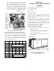
Not all available heater modules may be used in every unit.
Use only those heater modules that are UL listed for use in a
specific size unit. Refer to the label on the unit cabinet and
the unit data plate for the list of approved heaters. (See Fig. 1
and 2.) See Appendix D for electric heater module data.
NOTE: The following heaters do not use the slide track:
CRHEATER101A00-109A00, 297A00, 298A00, 301A00.
Single Point Boxes and Fuses
The Single Point Box (SPB) kits provide a field power
termination location plus an enclosure for heater fuses
when required by code. The SPBs are installed under the
unit’s main control box and include a cover plus all
internal wiring. Minimum components of the SPB are a
field power terminal block with tap conductors (to
connect to the unit’s main control box field terminals).
Maximum component population includes up to five fuse
blocks.
Fuses for electric heater circuits are required and provided
when the unit’s MOCP exceeds 60-A or when the total
heater Full Load Amp value exceeds 48-A. When fuses
are required and provided, the cooling circuit is also
provided with fuse protection; some units require minor
wiring changes in the main control box (see section on
TB10 terminal blocks).
No Fuses
If the unit’s MOCP device rating is 60-A or less, then the
MOCP device is recognized as providing the required
overcurrent protection to the heater and no internal fusing
is required. If two heater modules are installed, a single
point box that contains only a field power terminal block
is required. See tables at the beginning of Appendix A, B
and C for where-used information on the single point
boxes and for connections Figure number.
Units with Factory Installed HACR
The amp rating of the HACR factory installed option is
based on the size, voltage, indoor motor and other
electrical options of the unit as shipped from the factory.
When field installed accessory electric heaters are added
or changed in the unit, the HACR may no longer be of the
proper amp rating and therefore will need to be removed
from the unit. See unit nameplate and label on factory
installed HACR for the amp rating of the HACR that was
shipped with the unit from the factory. See unit
nameplates for the proper fuse, HACR or maximum
over--current protection device required on the unit with
field installed electric heat.
Single Point Box Contents
See Package Content tables for a list of components
included in each single point box kit. Note the height
differences and their use in specific size units.
Control Wiring
Heater modules contain one or two heater control
contactors. If two heater modules are installed, or a
two-circuit heater module is installed, the cooling unit
(AC type) can be connected for one-stage or two-stage
heating control. On all heat pump units (HP type), all
heater contactors will be connected to provide
second-stage heating control.