
Install Instructions


9
Terminal Block TB10 (208/230--V Units)
Two small terminal blocks (designated TB10) are
included in these single--point boxes used on select
208/230--3--60 units.
SPB PNO CRSINGLE
043A00
045A00
049A00
051A00
053A00
054A00
TB10 is a small single--pole terminal block, 2-1/2 in. (63
mm) long with seven ¼-in. male quick-connect terminals.
One or two terminal blocks are used to aid in rearranging
the unit’s base cooling power circuit into two circuits, each
under 60-A MOCP. On units using both TB10 blocks, the
indoor fan motor is separated into the second circuit. On
units using only a single TB10 block, Compressor 2 is
separated into the second circuit.
On the largest units and on all AC--3 (50LC) units, the
TB10 blocks are not used and may be discarded. The tap
conductors from fuse blocks FU2 and FU3 are connected
in parallel to the main control box’s power terminal block.
See unit--SPB connection figures in the Appendix section.
The following tables indicate TB10 use on AC--1, AC--2,
HP--1 and HP--2 units using these single point boxes:
AC--1
AC--1 SPB TB10 Qty
08 (090,091)
043A
045A
2
09 (101,102)
049A
051A
2
12 (120,121)
049A
051A
2
14 (150)
049A
051A
1
16 (180)
049A
051A
053A
NR
AC--2
AC--2 SPB TB10 Qty
07 (072) 043A 2
08 (090)
049A
051A
2
09 (102)
049A
051A
2
12 (120)
049A
051A
1
14 (150)
049A
051A
NR
HP--1
HP--1 SPB TB10 Qty
08 (090)
049A
051A
053A
2
09 (102)
049A
051A
053A
2
12 (120)
049A
051A
053A
054A
1
14 (150)
051A
053A
054A
NR
HP--2
HP--2 SPB TB10 Qty
07 (072)
043A
045A
2
08 (090)
049A
051A
053A
2
09 (102)
049A
051A
053A
054A
1
12 (120)
049A
051A
053A
054A
NR
GENERAL INSTALLATION
SEQUENCE
1. Pre--stage heater packages and single point boxes by
placing the required component cartons at each unit.
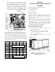
2. Check the heater sales package number and single
point box part number (if used) against the part
numbers on the unit’s infoplate. See Fig. 1 and 2 for
typical data.
3. Disconnect power wiring into unit control box from
factory--installed disconnect switch or HACR break-
er and withdraw wiring from control box.
4. Install the single point box and connect power
wiring tap conductors to field power terminals in
main control box.
5. Install the electric heater module(s) and connect
heater power conductors to single point box or main
unit control box per appropriate connections figure.
(See Appendix A, B and C.)
6. Connect the heater control contactors to unit termi-
nal block TB4.
7. Mark the unit infoplate to indicate which heater
module(s) have been installed.