
Install Instructions

2
SAFETY CONSIDERATIONS
Installation and servicing of air--conditioning equipment
can be hazardous due to system pressure and electrical
components. Only trained and qualified service personnel
should install, repair, or service air--conditioning
equipment.
Untrained personnel can perform the basic maintenance
functions. All other operations should be performed by
trained service personnel. When working on
air--conditioning equipment, observe precautions in the
literature, tags and labels attached to the unit, and other
safety precautions that may apply.
Follow all safety codes. Wear safety glasses and work
gloves.
Recognize safety information. This is the safety--alert
symbol
. When you see this symbol on the unit and in
instructions or manuals, be alert to the potential for
personal injury.
Understand the signal words DANGER, WARNING, and
CAUTION. These words are used with the safety--alert
symbol. DANGER identifies the most serious hazards
which will result in severe personal injury or death.
WARNING signifies a hazard which could result in
personal injury or death. CAUTION is used to identify
unsafe practices which may result in minor personal
injury or product and property damage. NOTE is used to
highlight suggestions which will result in enhanced
installation, reliability, or operation.
ELECTRICAL SHOCK HAZARD
Failure to follow this warning could result in personal
injury and/or death.
Before beginning any modification, disconnect power
supply and install lockout tag before attempting to
install the accessory. All wiring must comply with
applicable national and local codes.
!
WARNING
PERSONAL INJURY AND EQUIPMENT
DAMAGE HAZARD
Failure to follow this warning could result in personal
injury and/or death and damage to equipment.
Field modification of electric heat staging may result
in the overriding of electric heat safety switches and is
prohibited.
!
WARNING
GENERAL
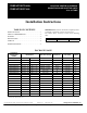
This installation instruction covers accessory heaters
CRHEATER270A through CRHEATER287A00. Each kit
contains the heater module, wire ties, and 3--1/4--20 nuts.
See Package Usage table for unit electrical data and kit
usage.
NOTE: All vertical supply units with electric heat require a
field--supplied 90--degree elbow. The elbow must be installed
in the supply ductwork below the unit discharged
connection.
NOTE: If Single Point power entry is desired when using
a 75kW 208/230 volt heater, the single point accessory
CRSINGLE056A00 must be used.
NOTE: For units equipped with a disconnect switch, the
disconnect must be adequately sized for the electric
heater. Refer to the unit’s nameplate or the Product Data
for the unit.
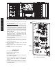
INSTALLATION
Heater Installation (All Units)
Perform the following procedure to install the accessory
electric heaters:
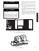
1. Turn off power to the unit.
2. Remove electric heater section access panel, control
box access panel, filter access panel, and blower
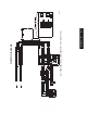
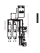
access panel from base rooftop unit. (See Fig. 1.)
Control Box
Access Panel
Filter Access
Panel
Blower
Access
Panel
Electric Heater Section
Access Panel
C09420
Fig. 1 -- Typical Unit – Access Panel Locations
CRHEATER270A00-- 287A00