
Specifications

25
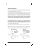
PRIMARY CIRCUIT WITH FURNACE BLOWER OPERATING
If there is supply line voltage at the connections and no input voltage to the
power supply, the outage can be located by checking operation of the
safety switch and the interconnecting wiring with a multimeter. Refer to
Circuit Diagram, (Figure 9) to check operation of the switches.
Following these steps to test for proper operation of the circuit board and
power supply assembly:
1. Ensure that the circuit breaker controlling the furnace blower is in the ON
position and the main fuse is not open.
2. The power supply board has a built-in internal fuse to protect the 24V
transformer. It can be checked visually by inspecting the fuse. If the fine
wire inside the fuse is broken, this indicates a problem in the 24V circuit of
the power supply board. Do NOT replace this fuse. The entire power
supply board must be replaced. The purpose of the fuse is not to protect
the power supply board, but to function as a troubleshooting feature of
the product and to protect the transformer from damage.
3. If the fuse is NOT blown, check the ON/OFF switches and safety interlock
switch for proper engagement and operation. This can be completed
using a volt ohm millimeter on a scale that will measure ohms as low as
1.0. If you are using the recommended meter previously mentioned in
this manual, set the meter to read 200 ohm and proceed with Steps 4
through 6.
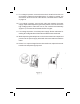
4. Remove the fuse. Connect one lead to the test pin located directly beside
the wire that connects the ON/OFF switch to the power supply board.
Connect the other lead to the fuse connection closest to the front panel.
5. Turn the ON/OFF switch to the ON position and depress the safety
interlock switch. The meter should have the capability of reading levels
as low as 1.0 ohm.
6. If there is no reading on the meter, begin the process of elimination by
disconnecting the wire from the test point and connecting it to the
terminal with the blue wire located on the safety interlock switch. Depress
the safety interlock switch. If the reading on the meter is greater than 1.0
ohm, the safety interlock switch is defective and must be replaced. If the
reading on the meter is less than 1.0 ohm, the ON/OFF switch is defective
and must be replaced.
27