
Specifications

13
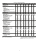
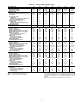
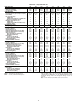
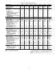
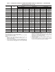
Table 1A — Physical Data, English (cont)
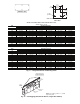
LEGEND *Charges listed are for 30HXC units. The 30HXA units are shipped
with a holding charge only. To determine the refrigerant charge
requirements for 30HXA units, see the 30HXA Estimated System
Refrigerant Charge table in the Refrigerant Charge section on
page 41.
†Only on units with factory-installed suction service valves.
UNIT SIZE 30HX 161 171 186 206 246 261 271
UNIT OPERATING WEIGHT (lb)
Water-Cooled (HXC) 7452 7660 7854 10,581 10,969 10,992 11,029
Condenserless (HXA) 5752 5777 5946 7,485 7,621 7,621 7,621
COMPRESSORS Semi-Hermetic, Twin Screw
Quantity 222 3 3 3 3
Nominal Capacity per Compressor (tons) 80/56 66/80 80/80 66/39/80 80/56/80 80/66/80 80/80/80
Economizer Yes Yes Yes Yes Yes Yes Yes
No. Capacity Steps
30HXC Unit 666 8 8 8 8
30HXA Unit (maximum on 30HXC unit
with factory-installed option) 8 8 811111111
Minimum Step Capacity (%)
30HXC Unit 20 20 20 13 13 13 13
30HXA Unit (30HXC unit with factory-
installed option) 10 10 10 7 7 7 7
REFRIGERANT (HXC) R-134a
Charge* (lb) Circuit A/Circuit B 157/110 119/140 135/135 200/135 220/135 220/135 220/135
COOLER TYPE Shell and Tube with Enhanced Copper Tubes
Part No. 10HX400- 601 611 621 631 632 632 632
Net Fluid Volume (gal) 28.5 28.5 33.4 43.1 47.2 47.2 47.2
Maximum Refrigerant Pressure (psig) 220 220 220 220 220 220 220
Maximum Water-Side Pressure (psig) 300 300 300 300 300 300 300
Water Connections
Inlet and Outlet (in.) (Std Pass) 555 6 6 6 6
Drain (NPT) (Std Pass)
3
/
8
3
/
8
3
/
8
3
/
8
3
/
8
3
/
8
3
/
8
Relief Valve
Connection (in. NPTF)
3
/
4
3
/
4
3
/
4
3
/
4
3
/
4
3
/
4
3
/
4
Flow Capacity (lb air/min) 31.7 31.7 31.7 31.7 31.7 31.7 31.7
Relief Setting (psig) 220 220 220 220 220 220 220
Standard Number of Passes 222 2 2 2 2
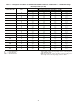
OIL SEPARATOR (HXA)
Part No. 09RX400- 215 214 214 213 213 213 213
Maximum Refrigerant Pressure (psig) 320 320 320 320 320 320 320
Refrigerant Connections (in.)
Discharge Circuit A/Circuit B 2
1
/
8
/2
1
/
8
2
1
/
8
/2
1
/
8
2
1
/
8
/2
1
/
8
(2) 2
1
/
8
/2
1
/
8
(2) 2
1
/
8
/2
1
/
8
(2) 2
1
/
8
/2
1
/
8
(2) 2
1
/
8
/2
1
/
8
Liquid Circuit A/Circuit B 1
3
/
8
/1
3
/
8
1
3
/
8
/1
3
/
8
1
3
/
8
/1
3
/
8
1
5
/
8
/1
3
/
8
1
5
/
8
/1
3
/
8
1
5
/
8
/1
3
/
8
1
5
/
8
/1
3
/
8
Relief Valve
Connection (in. SAE Flare)
5
/
8
5
/
8
5
/
8
5
/
8
5
/
8
5
/
8
5
/
8
Flow Capacity (lb air/min) 21.6 21.6 21.6 21.6 21.6 21.6 21.6
Relief Setting (psig) 320 320 320 320 320 320 320
CONDENSER (HXC) Shell and Tube with Enhanced Copper Tubes
Part No. 09RX400- 261 262 262 263 264 264 264
Net Fluid Volume (gal) 30.6 37.6 37.6 47.6 55.1 55.1 55.1
Maximum Refrigerant Pressure (psig) 220 220 220 220 220 220 220
Maximum Water-Side Pressure (psig) 300 300 300 300 300 300 300
Water Connections (in.) Victaulic Type Connection
Inlet and Outlet (Std Pass) 666 8 8 8 8
Drain (NPT) (Std Pass)
3
/
8
3
/
8
3
/
8
3
/
8
3
/
8
3
/
8
3
/
8
Relief Valve
Connection (in. NPTF)
3
/
4
3
/
4
3
/
4
3
/
4
3
/
4
3
/
4
3
/
4
Flow Capacity (lb air/min) 31.7 31.7 31.7 31.7 31.7 31.7 31.7
Relief Setting (psig) 220 220 220 220 220 220 220
Standard Number of Passes 222 2 2 2 2
DISCHARGE LINE†
Relief Valve
Connection (in. SAE Flare)
3
/
8
3
/
8
3
/
8
3
/
8
3
/
8
3
/
8
3
/
8
Flow Capacity (lb air/min) 6.3 6.3 6.3 6.3 6.3 6.3 6.3
Setting (psig) 350 350 350 350 350 350 350
NPTF — National Pipe Thread Female
SAE — Society of Automotive Engineers