30GXN,R080-528 30HXA,HXC076-271 Air-Cooled and Water-Cooled Chillers with ComfortLink™ Controls 50/60 Hz Series 6 Controls Start-Up, Operation, Service, and Troubleshooting SAFETY CONSIDERATIONS Installing, starting up, and servicing this equipment can be hazardous due to system pressures, electrical components, and equipment location (roof, elevated structures, etc.). Only trained, qualified installers and service mechanics should install, start up, and service this equipment.
Page • INSPECTING/OPENING ELECTRONIC EXPANSION VALVES • BRAZED-PLATE ECONOMIZERS SERVICE . . . . . . . . . . . . . . . . . . . . . . . . . . . . . . . . . . . . . 52-71 Servicing Coolers and Condensers. . . . . . . . . . . . . . 52 • TUBE PLUGGING • RETUBING • TIGHTENING COOLER/CONDENSER HEAD BOLTS Inspecting/Cleaning Heat Exchangers . . . . . . . . . . . 52 • COOLERS • CONDENSERS (30HX Only) Water Treatment . . . . . . . . . . . . . . . . . . . . . . . . . . . . . . . . . 53 Condenser Coils (30GXN,R Only).
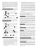
CONTENTS (cont) ComfortLink Compressor Protection (CCP) Board — The CCP board monitors the high-pressure Page switch status, running current and motor temperature for each compressor. Each CCP board controls up to 2 compressors. The CCP board also controls the motor cooling solenoid, oil solenoid and contactor outputs. A pre-punched configuration header for each compressor determines the must trip amps setting.
Carrier Comfort Network (CCN) Interface — OPERATION DATA Electronic Expansion Valve (EXV) — The The 30GXN,R and 30HX chiller units can be connected to the CCN if desired. The communication bus wiring is a shielded, 3-conductor cable with drain wire and is supplied and installed in the field. The system elements are connected to the communication bus in a daisy chain arrangement.
OIL FEED TO COMPRESSOR MOTOR COOLING SOLENOID CHECK VALVE TXV BULB OIL SUPPLY LINE TO PUMP OIL PUMP TXV SOLENOID (30GXN,R ONLY) OIL SEPARATOR FILTER BRAZED PLATE ECONOMIZER Fig. 3 — Oil Pump Fig. 2 — Brazed Plate Economizer The increase in performance is achieved by diverting a small amount of liquid through a thermostatic expansion valve to a second circuit in the brazed-plate heat exchanger. This will further subcooling the liquid in the first circuit as the refrigerant flashes to vapor.
separator is not at least 15 psig greater than the economizer pressure. Back Pressure Valve (30GXN,R and 30HXA only) — This valve is located on the oil separator outlet on 30GXN,R units and mounted on the oil separator shell of 30HXA units. The valve’s function is to ensure that there is sufficient system differential pressure to allow for oil to be driven back to the compressor.
INPUTS: • motor temperature • three-phase current • high-pressure switch A diagram of the CCP board is shown in Fig. 4. One CCP board is installed on 30GXN,R080-178 and 30HXA,C076-186 units and two CCP boards are installed on 30GXN,R204-350 and 30HXA,C206-271 units. The address for each CCP board is set using DIP (dual in-line package) switches. For CCP1 (compressor A1 and B1), DIP switch 1 should be set to ‘L’ (‘On’ position for LEN communication). Switches 2, 3 and 4 should be set to ‘0’ (“OFF” position).
Position 12 in model number) are supplied with factoryinstalled Wye-Delta starters. All other voltage options can be ordered with either Wye-Delta or XL starting options. The XL starting method is the most cost effective and simply starts the compressor motor in a Delta configuration (the motors are designed for continuous operation in this configuration) using a single contactor. See Fig. 5. This is the simplest starting method to use and is ideal where starting current does not require limiting.
COMPRESSOR JUNCTION BOX COMPRESSOR CONTACTOR TERMINAL BLOCK 1 1 21 L1 T1 L2 T1 L3 T3 2 2 22 2 4 3 3 23 6 1 5 3 JUMPER BARS Fig. 5 — Across-the-Line (XL) Compressor Wiring 1 1 21 T1 L1 2 L2 22 3 23 COMPRESSOR JUNCTION BOX COMPRESSOR STARTER ASSEMBLY TERMINAL BLOCK 6 4 2 1M T2 3 L3 T3 L1 T1 1 6 2 4 3 5 21 L2 T2 2M T3 L3 23 T1 L1 L2 22 S T2 5 T3 L3 Fig. 6 — Wye-Delta Compressor Wiring required to maintain better leaving fluid temperature regulation.
6. Adjust the minimum load ball valve until the cooler temperature difference reading from Step 5 is equal to half of the temperature difference reading from Step 3. 7. Open the ball valve to decrease the temperature difference or close the ball valve to increase the temperature difference (T).
2 STARTS DEADBAND EXAMPLE 47 7 6 46 45 LWT (F) LWT (C) 8 44 43 42 5 41 0 200 400 600 TIME (SECONDS) 800 1000 3 STARTS STANDARD DEADBAND LEGEND LWT — Leaving Water Temperature MODIFIED DEADBAND Fig. 7 — Deadband Multiplier fan cycling pressure switches (shipped in the 30HXA control box), temperature switches, and an accessory Motormaster® control to maintain head pressure independent of 30HXA unit control.
(HPCT under sub-mode OPT1) must be configured to 1 (aircooled), and Condenser Pump control must be set to 0 (CNPC must be set to No control, Configuration mode under sub-mode OPT1). Low ambient head pressure control can be accomplished with fan cycling pressure switches (09DK054-094), temperature switches (09DK044, 074-094), and Motormaster® control. The Motormaster control requires a temperature sensor input to control condenser fan cycling.
Table 7 — Fan Staging Select Configuration Settings for Air Cooled (30GXN,R) Units UNIT 30GXN,R COMPUTER SOFTWARE DISPLAY NAVIGATOR DISPLAY 080,090* 6 (1 STAGE COM) 083,093,106,108, 114,125,135* 118,128,138, 150,160* 7 (2 STAGE COM) 8 (3 STAGE COM) 153,174, 204,225* 4 (A2B1 IND) 163,178* 2 (2 STAGE IND) 249,264* 5 (A3B2 IND) 208,228 253,268,281-350* 3 (3 STAGE IND) DESCRIPTION 1st stage compressor status and SCT set point 2nd stage common control based on highest SCT 1st stage compres
30GXN,R UNITS — MOTORMASTER V CONTROL NOT INSTALLED LEGEND SCT — Saturated Condensing Temperature Fig. 9A — 30GXN,R Units Head Pressure Control Without Motormaster® V Control 30GXN,R UNITS — MOTORMASTER V CONTROL INSTALLED IS SCT GREATER THAN HEAD PRESSURE SET POINT PLUS 15°F (8.3°C)? READ CIRCUIT SATURATED CONDENSING TEMPERATURE AND CURRENT FAN STAGE NO CALCULATE NEW PID VALUE.
Table 9 — 30GXN,R080-350 Condenser Fan Staging (Main Base Board Controlled) 30GXN,R UNIT SIZE FAN TYPE Standard 080, 090 High Static Standard 083, 093, 106-114, 125, 135 High Static Standard 118, 128, 138, 150, 160 High Static Standard 153, 174, 204, 225 High Static Standard 163, 178 High Static Standard 249, 264 High Static Standard 208, 228 High Static Comp.
Table 9 — 30GXN,R080-350 Condenser Fan Staging (Main Base Board Controlled) (cont) 30GXN,R UNIT SIZE FAN TYPE Standard 253, 268 High Static Standard 281-350 High Static NAVIGATOR OUTPUT POINT NAME Comp. B1 contactor* Fan 1 Fan 2 Fan 4 Fan 3 Comp. A1/A2 contactor* Fan 3 Fan 3 Fan 1 Comp. B1 contactor* Fan 1 Fan 2 Fan 4 Fan 3 Comp. A1/A2 contactor* Fan 3 Fan 3 Fan 1 Comp. B1/B2 contactor* Fan 2 Fan 4 Fan 4 Fan 1 Comp. A1/A2 contactor* Fan 3 Fan 3 Comp. B1/B2 contactor* Fan 2 Fan 4 Fan 4 Fan 1 Comp.
REMOTE position. The unit can be enabled and disabled by this action or all control methods. 7-DAY SCHEDULE — Unit is started and stopped in accordance with the schedule configured under Time Clock mode. This schedule can be configured from the Navigator or from CCN. OCCUPANCY — Unit is started and stopped in accordance with the local occupancy schedule accessible only from CCN.
When there is chilled water flow, but the flow is inadequate to close the switch and allow unit operation, one red LED will illuminate. A red LED can also indicate inoperative pump(s), closed valve, clogged strainer or air in the system. When the first green LED is illuminated, the switch is closed and the unit will start and run. Various conditions can cause variations in flow and allow the switch to open and cause a “nuisance trip”. Greater constant flow will help reduce nuisance tips.
Co m NA T IM E EWT LW T SETP MO fort VIG Two items, OAT Outside Air Temperature (Temperature Mode, Sub-mode UNIT) and SPT Space Temperature (Temperature Mode, Sub-mode UNIT) can be forced to a value at the Navigator. If one of these two points has been forced, a flashing “f” will appear next to the value indicating a forced value. To remove the force, select the item and press the ENTER key so that the value is flashing. Press the up and down arrow keys simultaneously and the force will be removed.
RETURN FLUID SLAVE CHILLER MASTER CHILLER point of the slave chiller. The master chiller will also split demand limiting function appropriately between the two chillers, if demand limiting is enabled. The master chiller is now configured for dual chiller operation. To configure the slave chiller, only the LLEN, PARA and MSSL variables need to be set. Enable the Lead/Lag chiller variable (LLEN) as shown in Tables 24A and 24B. Similarly, set the Master/Slave Select variable (MSSL) to SLVE.
Table 12 — Configuration Mode and Sub-Mode Directory SUBMODE DISP UNIT KEYPAD ENTRY ENTER ENTER ITEM DISPLAY TEST ON/OFF ITEM EXPANSION TEST DISPLAY LEDs METR ON/OFF METRIC DISPLAY LANG X LANGUAGE SELECTION PAS.E ENBL/DSBL PASSWORD ENABLE PASS XXXX SERVICE PASSWORD TYPE X UNIT TYPE COMMENT See Backlight and Contrast adjustment in Tables 21 and 22.
Table 12 Configuration Mode and Sub-Mode Directory (cont) SUBMODE OPT1 OPT2 KEYPAD ENTRY ENTER ENTER ITEM DISPLAY FLUD X ITEM EXPANSION COOLER FLUID MLVS YES/NO MIN LOAD VALVE SELCT HPCT X HEAD PRESS CONTROL TYPE VHPT X VAR HEAD PRESSURE SELECT PRTS YES/NO PRESSURE TRANSDUCERS COMMENT Default: Water Water Medium Temperature Brine Low Temperature Brine (30HX only) Minimum Load Valve No Control Air Cooled (30GXN,R, 30HXA default) Water Cooled (30HXC default) Common Cond (30HXA Common Co
Table 12 Configuration Mode and Sub-Mode Directory (cont) SUBMODE RSET KEYPAD ENTRY ENTER ITEM DISPLAY CRST X ITEM EXPANSION COOLING RESET TYPE CRT1 XXX.X °F NO COOL RESET TEMP CRT2 XXX.X °F FULL COOL RESET TEMP DGRC XX.X F DEGREES COOL RESET HRST X HEATING RESET TYPE HRT1 XXX.X °F NO HEAT RESET TEMP HRT2 XXX.X °F FULL HEAT RESET TEMP DGRH XX.
Table 12 Configuration Mode and Sub-Mode Directory (cont) SUB MODE SLCT SERV BCST KEYPAD ENTRY ENTER ENTER ENTER ITEM DISPLAY CLSP X ITEM EXPANSION COOLING SETPOINT SELECT HTSP X HEATING SETPOINT SELECT COMMENT Default: Single Single Dual Switch Dual 7 day Dual CCN Occupied 4 to 20 mA Input (requires EMM) Default: Single Single Dual Switch Dual 7 day Dual CCN Occupied 4 to 20 mA Input (requires EMM) RL.S ENBL/DSBL RAMP LOAD SELECT CRMP X.X COOLING RAMP LOADING HRMP X.
Table 13 — Service Test Mode and Sub-Mode Directory SUBMODE TEST OUTS COMP KEYPAD ENTRY ON/OFF ITEM EXPANSION SERVICE TEST MODE EXV.A XXX % EXV % OPEN VH.PA XXX % VAR HEAD PRESS % OL.P.A ON/OFF OIL PUMP MC.A1 ON/OFF MOTOR COOLING SOLENOID A1 MC.A2 ON/OFF MOTOR COOLING SOLENOID A2 OS.A1 ON/OFF OIL SOLENOID A1 OS.A2 ON/OFF OIL SOLENOID A2 EXV.B XXX % EXV % OPEN VH.PB XXX % VAR HEAD PRESS % OL.P.B ON/OFF OIL PUMP MC.B1 ON/OFF MOTOR COOLING SOLENOID B1 MC.
Table 14 — Temperature Mode and Sub-Mode Directory SUB-MODE KEYPAD ENTRY ITEM DISPLAY ITEM EXPANSION UNIT ENTER CEWT XXX.X °F COOLER ENTERING FLUID CLWT XXX.X °F COOLER LEAVING FLUID OAT XXX.X °F OUTSIDE AIR TEMPERATURE SPT XXX.X °F SPACE TEMPERATURE CNDE XXX.X °F CONDENSER ENTERING FLUID CNDL XXX.X °F CONDENSER LEAVING FLUID DLWT XXX.X °F LEAD/LAG LEAVING FLUID SCT.A XXX.X °F SATURATED CONDENSING TMP SST.A XXX.X °F SATURATED SUCTION TEMP SH.A XXX.
Table 15 — Pressure Mode and Sub-Mode Directory SUB-MODE KEYPAD ENTRY ITEM DISPLAY ITEM EXPANSION PRC.A ENTER DP.A XXX.X PSIG DISCHARGE PRESSURE SP.A XXX.X PSIG SUCTION PRESSURE ECN.A XXX.X PSIG ECONOMIZER PRESSURE OP.A1 XXX.X PSIG A1 OIL PRESSURE OP.A2 XXX.X PSIG A2 OIL PRESSURE DO.A1 XXX.X PSI A1 OIL PRESSURE DIFF. DO.A2 XXX.X PSI A2 OIL PRESSURE DIFF. FD.A1 XXX.X PSI A1 OIL FILTER DIFF. PRESS FD.A2 XXX.X PSI A2 OIL FILTER DIFF. PRESS PS.A1 XX.
Table 17 — Inputs Mode and Sub-Mode Directory SUB-MODE KEYPAD ENTRY ITEM DISPLAY ITEM EXPANSION GEN.I ENTER STST STRT/STOP START/STOP SWITCH FLOW ON/OFF COOLER FLOW SWITCH CND.F ON/OFF CONDENSER FLOW SWITCH DLS1 ON/OFF DEMAND LIMIT SWITCH 1 DLS2 ON/OFF DEMAND LIMIT SWITCH 2 ICED ON/OFF ICE DONE DUAL ON/OFF DUAL SETPOINT SWITCH FKA1 ON/OFF COMPRESSOR A1 FEEDBACK FKA2 ON/OFF COMPRESSOR A2 FEEDBACK OIL.A OPEN/CLSE OIL LEVEL SWITCH A1.
Table 18 — Outputs Mode and Sub-Mode Directory SUB-MODE KEYPAD ENTRY ITEM DISPLAY ITEM EXPANSION GEN.O ENTER FAN1 ON/OFF FAN 1 RELAY FAN2 ON/OFF FAN 2 RELAY FAN3 ON/OFF FAN 3 RELAY FAN4 ON/OFF FAN 4 RELAY MLV ON/OFF MINIMUM LOAD VALVE C.PMP ON/OFF COOLER PUMP RELAY C.HT ON/OFF COOLER HEATER CNDP ON/OFF CONDENSER PUMP RELAY SMZ X.X LOAD/UNLOAD FACTOR CC.A1 ON/OFF COMPRESSOR A1 RELAY CC.A2 ON/OFF COMPRESSOR A2 RELAY LD.A1 ON/OFF LOADER A1 RELAY LD.
Table 19 — Operating Mode and Sub-Mode Directory SUB-MODE KEYPAD ENTRY ITEM DISPLAY ITEM EXPANSION MODE ENTER MD01 ON/OFF CSM CONTROLLING CHILLER MD02 ON/OFF WSM CONTROLLING CHILLER MD03 ON/OFF MASTER/SLAVE CONTROL MD04 ON/OFF LOW SOURCE PROTECTION MD05 ON/OFF RAMP LOAD LIMITED MD06 ON/OFF TIMED OVERRIDE IN EFFECT MD07 ON/OFF LOW COOLER SUCTION TEMPA MD08 ON/OFF LOW COOLER SUCTION TEMPB MD09 ON/OFF SLOW CHANGE OVERRIDE MD10 ON/OFF MINIMUM OFF TIME ACTIVE MD11 ON/OFF LO
Table 20 — Run Status Mode and Sub-Mode Directory SUB-MODE KEYPAD ENTRY ITEM DISPLAY ITEM EXPANSION VIEW ENTER EWT XXX.X °F ENTERING FLUID TEMP LWT XXX.X °F LEAVING FLUID TEMP SETP XXX.X °F ACTIVE SETPOINT CTPT XXX.X °F CONTROL POINT STAT X CONTROL MODE OCC YES/NO OCCUPIED MIN.L XX MIN MINUTES LEFT FOR START MODE YES/NO OVERRIDE MODES IN EFFECT CAP XXX % PERCENT TOTAL CAPACITY DEM.L XXX % ACTIVE DEMAND LIMIT ALRM XXX CURRENT ALARMS & ALERTS TIME XX.
Table 20 — Run Status Mode and Sub-Mode Directory (cont) SUB-MODE VERS KEYPAD ENTRY ENTER ITEM ITEM EXPANSION DISPLAY COMMENT MBB CESR-131344-xx-xx xx-xx is Version number EXV CESR-131172-xx-xx xx-xx is Version number EMM CESR-131174-xx-xx xx-xx is Version number CP1 100233-1R1-xx-xx xx-xx is Version number CP2 100233-1R1-xx-xx xx-xx is Version number SCB CESR-131226-xx-xx xx-xx is Version number NAVI CESR-131227-xx-xx xx-xx is Version number Table 21 — How to Adjust Navigator Bac
Table 23 — Time Clock Mode and Sub-Mode Directory SUB-MODE KEYPAD ENTRY ITEM DISPLAY ITEM EXPANSION TIME ENTER HH.MM XX.XX HOUR AND MINUTE Military (00:00 — 23:59) MNTH XX MONTH OF YEAR January, February, etc. DOM XX DAY OF MONTH DAY X DAY OF WEEK YEAR XXXX YEAR STR.M XX MONTH STR.W X WEEK STR.D X DAY MIN.A XX MINUTES TO ADD STP.M XX MONTH STP.W XX WEEK STR.D XX DAY MIN.5 XX MINUTES TO SUBTRACT MON.O XX.XX MONDAY OCCUPIED TIME MON.U XX.
Table 24A — Example of Configuring Dual Chiller Control (Master Chiller) SUB-MODE ITEM KEYPAD ENTRY DISPLAY OPT2 OPT2 ENTER CTRL ENTER SWITCH CTRL ENTER SWITCH CCNA ENTER 1 CCNA ENTER 1 CCNB ENTER 0 CCNB ENTER 0 CCNB ESCAPE OPT2 RSET ENTER ITEM EXPANSION VALUE FLASHES CONTROL METHOD CRST SEE NOTE 1 DEFAULT 1 CCN ADDRESS CHANGE IF REQUIRED DEFAULT 0 CCN BUS NUMBER RESET RSET COMMENT CHANGE IF REQUIRED PROCEDE TO SUBMODE RSET NO RESET COOLING RESET TYPE 15 ITEMS LLEN
Table 24B — Example of Configuring Dual Chiller Control (Slave Chiller) SUB-MODE ITEM KEYPAD ENTRY OPT2 OPT2 ENTER DISPLAY ITEM EXPANSION CTRL ENTER SWITCH CONTROL METHOD ESCAPE SWITCH ESCAPE CTRL CTRL CCNA CCNA COMMENT SEE NOTE 1 CCNA ENTER 1 ENTER 1 VALUE FLASHES 2 SELECT 2 (SEE NOTE 2) ENTER 2 ESCAPE CCNA CCN ADDRESS CCN ADDRESS SCROLLING STOPS CHANGE ACCEPTED CCNB CCNB ENTER 0 ESCAPE CCNB ESCAPE OPT2 CCN BUS NUMBER RSET RSET RSET LLEN LLEN ENTER PROCEED TO
Alarms/Alerts — Alarms and alerts are messages that one or more faults have been detected. The alarms and alerts indicate failures that cause the unit to shut down, terminate an option (such as reset) or result in the use of a default value such as a set point. Refer to the Troubleshooting section for more information. Up to 25 alarms/alerts can be displayed in currently active alarms. Up to 50 alarms/alerts can be stored in the alarm history. See Tables 25 and 26 to view and clear alarms.
Table 27 — Configuring Temperature Reset MODE CONFIGURATION KEYPAD KEYPAD ENTRY SUB-MODE ENTRY ITEM DISPLAY ITEM EXPANSION DISP ENTER TEST ON/OFF TEST DISPLAY LEDs UNIT ENTER TYPE X UNIT TYPE OPT1 ENTER FLUD X COOLER FLUID OPT2 ENTER CTRL X CONTROL METHOD CRST X COOLING RESET TYPE ENTER RSET ENTER CRT1 CRT2 DGRC COMMENT 0 = No Reset 1 = 4 to 20 mA Input (EMM required) (Connect to EMM J6-2,5) 2 = Outdoor-Air Temperature (Connect to TB5-7,8) 3 = Return Fluid 4 = Space Tempera
percentages. The second type is by 4 to 20 mA signal input which will reduce the maximum capacity linearly between 100% at a 4 mA input signal (no reduction) down to the user-configurable level at a 20 mA input signal. The third type uses the CCN Loadshed module and has the ability to limit the current operating capacity to maximum and further reduce the capacity if required. NOTE: The 2-stage switch control and 4- to 20-mA input signal types of demand limiting require the Energy Management Module (EMM).
reduce the current stages by the value entered for Loadshed Demand delta. The Maximum Loadshed Time is the defines the maximum length of time that a loadshed condition is allowed to exist. The control will disable the Redline/Loadshed command if no Cancel command has been received within the configured maximum loadshed time limit. Cooling Set Point (4 to 20 mA) — Unit operation is based on an external 4 to 20 mA signal input to the Energy Management Module (EMM). The signal is connected to TB6-3,5 (+,–).
Table 29 — Configuring Demand Limit MODE CONFIGURATION KEYPAD ENTRY SUB-MODE KEYPAD ENTRY ITEM DISPLAY ITEM EXPANSION ENTER DISP ENTER TEST ON/OFF Test Display LEDs UNIT ENTER TYPE X Unit Type OPT1 ENTER FLUD X Cooler Fluid OPT2 ENTER CTRL X Control Method RSET ENTER CRST X Cooling Reset Type CRT1 XXX.X °F No Cool Reset Temperature CRT2 XXX.X °F Full Cool Reset Temperature DGRC XX.
shut down immediately and EXV closes. Refer to Table 31 for typical stoppage faults and reset types. TROUBLESHOOTING The 30GXN,R and 30HX screw chiller control has many features to aid in troubleshooting. By using the Navigator control, operating conditions of the chiller can be viewed while the chiller is running. The Service Test function allows for testing of all outputs and compressors. Verify that the chiller is properly configured, including options and/or accessories, using the Configuration mode.
fault condition for a compressor alert is included as part of the alert description displayed on the Navigator. Press ENTER and ESCAPE simultaneously to display description. Compressor Alarm/Alert Circuit — Each compressor is directly controlled by a CCP module. Compressor faults (T051, T052, T055, T056) are reported as alerts.
Table 32 Alarm and Alert Codes (cont) ALARM/ALERT CODE A034 ALARM OR WHY WAS THIS ALARM ACTION TAKEN BY DESCRIPTION ALERT GENERATED? CONTROL Alarm Comp. A1 Max. Oil (Discharge press – Oil press) Comp. A1 shut down Delta P, check oil line > 100 PSI for more than 5 seconds A035 Alarm Comp. A2 Max. Oil (Discharge press – Oil press) Comp. A2 shut down Delta P, check oil line > 100 PSI for more than 5 seconds A036 Alarm Comp. B1 Max. Oil (Discharge press – Oil press) Comp.
Table 32 Alarm and Alert Codes (cont) ALARM/ALERT CODE T051 T052 T055 T056 ALARM OR WHY WAS THIS ALARM ACTION TAKEN BY DESCRIPTION ALERT GENERATED? CONTROL Alert Compressor A1 Failure – (See below) Alert Compressor A2 Failure – (See below) See additional descriptions below. Alert Compressor B1 Failure – (See below) Alert Compressor B2 Failure – (See below) Manual No Motor Current Comp. shut down Manual CCP measures current Circuit shut down imbalance between phases must be above C.
Table 32 Alarm and Alert Codes (cont) ALARM/ ALERT CODE T071 ALARM OR DESCRIPTION ALERT Alert Cir.
Table 32 Alarm and Alert Codes (cont) ALARM/ ALARM OR DESCRIPTION ALERT CODE ALERT T120 Alert Circuit A Low Saturated Suction Temperature WHY WAS THIS ALARM GENERATED? SST reads 6° F (3.3° C) or more below the brine freeze point for 3 minutes or 28° F below brine freeze point for 2 minutes. SST reads 6° F (3.3° C) or more below the brine freeze point for 3 minutes or 28° F below brine freeze point for 2 minutes. After first 90 seconds, SST > 55 F (12.8 C) and EXV < 1% for 5 minutes.
Table 32 Alarm and Alert Codes (cont) ALARM/ALERT ALARM OR WHY WAS THIS DESCRIPTION CODE ALERT ALARM GENERATED? T142 Alert Compressor B1 – Oil filter pressure drop High Oil Filter Pressure (FD.B1) exceeds 25 psig Drop (172 kPa) for water-cooled units or 30 psig (207 kPa) for air-cooled and split system units. T143 Alert Compressor B2 – Oil filter pressure drop High Oil Filter Pressure (FD.B2) exceeds 25 psig Drop (172 kPa) for water-cooled units or 30 psig (207 kPa) for air-cooled and split system units.
Table 32 Alarm and Alert Codes (cont) ALARM/ALERT ALARM OR DESCRIPTION CODE ALERT T182 Alert Compressor Protection Module 1 Internal Diagnostic T183 Alert Compressor Protection Module 2 Internal Diagnostic T184 Alarm T185 Alarm A200 Alarm A201 Alarm` Compressor Protection Module 1 Compressor Protection Module 2 Cooler Pump Interlock Failed at Start-Up Cooler Pump Interlock Opened Unexpectedly A202 Alarm Cooler Pump Interlock Closed When Pump OFF T203 Alert Loss of Communication with the S
LEGEND AND NOTES FOR TABLE A/D CCN CCP EMI EMM EWT EXV HPS LCW LWT MBB MCT_SP MTA SCB SCT SST TXV WSM — — — — — — — — — — — — — — — — — — LEGEND Analog to Digital Converter Carrier Comfort Network ComfortLink™ Compressor Protection Electromagnetic Interference Energy Management Module Entering Water Temperature Electronic Expansion Valve High-Pressure Switch Leaving Chilled Water Leaving Water Temperature Main Base Board Maximum Condensing Temperature Set Point Compressor Must Trip Amps Screw Compressor B
INSPECTING/OPENING ELECTRONIC EXPANSION VALVES EXV Troubleshooting Procedure — Follow steps below to diagnose and correct EXV/Economizer problems. Check EXV motor operation first. Switch the Enable/Off/ Remote (EOR) Contact switch to the Off position. Press ESCAPE on the Navigator until ‘Select a menu item’ appears on the display. Use the arrow keys to select the Service Test mode. Press ENTER . The display will be: > TEST OFF OUTS COMP IMPORTANT: Obtain replacement O-ring before opening EXV.
BRAZED-PLATE ECONOMIZERS — Brazed-plate economizers are factory-installed in each circuit on 30GXN,R108, 118-350 and 30HXA,C161-271 models. A TXV is included to meter the flow of refrigerant to the economizer port of the compressor. Flow through the TXV is enabled only when the circuit is fully loaded for 30GXN,R models. The TXV bulb is secured to the side of the economizer outlet tube. See Fig. 22 for typical piping arrangement. Brazed-plate heat exchangers cannot be repaired if they develop a leak.
SERVICE Servicing Coolers and Condensers — When cool- er heads and partition plates are removed, tube sheets are exposed showing the ends of tubes. The 30GXN,GXR,HX units use a flooded cooler design. Water flows inside the tubes. TUBE PLUGGING — A leaky tube in one circuit can be plugged until retubing can be done. The number of tubes plugged determines how soon the cooler must be retubed. All tubes in the 30GXN,R and 30HX coolers and 30HX condensers can be removed.
10 11 9 6 9 5 6 5 NOZZLE 3 2 3 1 4 1 8 11 10 9 3 3 2 2 4 7 14 13 11 9 6 5 6 12 8 7 12 10 5 10 12 16 14 2 NOZZLE 1 12 1 4 14 8 7 8 13 7 13 11 4 15 Fig. 25 — Cooler and Condenser Head Recommended Bolt Torque Sequence CONDENSERS (30HX Only) — Since this water circuit is usually an open-type system, the tubes may be subject to contamination and scale.
7. Thoroughly rinse all surfaces with low velocity clean water using downward rinsing motion of water spray nozzle. Protect fins from damage from the spray nozzle. Remove Surface Loaded Fibers — Surface loaded fibers or dirt should be removed with a vacuum cleaner. If a vacuum cleaner is not available, a soft brush may be used. In either case, the tool should be applied in the direction of the fins. Coil surfaces can be easily damaged (fin edges bent over) if the tool is applied across the fins.
2. At these operating conditions, check the liquid line sight glass. If there is a clear sight glass, then the unit has sufficient charge. If the sight glass is flashing, then check the EXV Percent Open. If this is greater than 60%, then begin adding charge. NOTE: A flashing liquid line sight glass at operating conditions other than those mentioned above is not necessarily an indication of low refrigerant charge. 3. Add 5 lb (2.
TEMPERATURE MEASUREMENT (CIRCUIT B) Addition of oil charge to 30HX,GXN,GXR systems: 1. If the 30HX,GXN,GXR unit shuts off repeatedly on Low Oil Level (Alert number 124 or 125), this may be an indication of inadequate oil charge. It could also mean simply that oil is in the process of being reclaimed from the low-side of the system. 2. Begin by running the unit at full load for 11/2 hours. Use the Manual Control feature of the software if the unit does not normally run at full load. 3.
shutoff valve (if equipped) for circuit to be changed. Disconnect the oil inlet line from the compressor. Disconnect oil filter with fitting at shutoff valve side and set filter and compressor inlet line assembly aside. 3. Remove any remaining refrigerant in the compressor and refrigerant lines using proper reclaiming techniques. All of the refrigerant that is in the cooler must be removed if there is no suction service valve installed on the cooler. 11. If low oil level problems persist, add another 1.
13. After checking to ensure all lines, wires, conduits, etc. are free and out of the way, remove compressor from cooler. Apply a light film of O-ring grease to new O-ring and place back into groove in mounting flange of compressor. If the new compressor is the A1/A2 (30HX units), A2 (30GXN,R204-268 units) or B2 (30GXN,R281-350 units) compressor, remove the compressor junction box and rotate it 180 degrees. Tighten screws to 6.8 to 9.5 N-m (5 to 7 ft-lb).
HPS Moisture-Liquid Indicator — Clear flow of liquid refrigerant indicates sufficient charge in the system. Note, however, that bubbles in the sight glass do not necessarily indicate insufficient charge. Moisture in the system is measured in parts per million (ppm), changes of color of indicator are: Green — moisture is below 80 ppm; Yellow-green (chartreuse) — 80 to 225 ppm (caution); Yellow (wet) — above 225 ppm. Change filter drier at the first sign of moisture in the system.
To Service Compressor Motor Thermistors — Two thermistors are factory installed in each compressor. Connections for the thermistors are located in the compressor junction box. There are 3 terminals for the thermistors: S1, S2, and C. Motor temperature is measured by leads connected to one of the S terminals and the C terminal. If a compressor motor thermistor failure occurs, verify that there is a true short or open circuit at these ter- minals.
Table 38A — 5K Thermistor Temperature (°F) vs Resistance/Voltage TEMP (F) –25 –24 –23 –22 –21 –20 –19 –18 –17 –16 –15 –14 –13 –12 –11 –10 –9 –8 –7 –6 –5 –4 –3 –2 –1 0 1 2 3 4 5 6 7 8 9 10 11 12 13 14 15 16 17 18 19 20 21 22 23 24 25 26 27 28 29 30 31 32 33 34 35 36 37 38 39 40 41 42 43 44 45 46 47 48 49 50 51 52 53 54 55 56 57 58 VOLTAGE DROP (V) 3.699 3.689 3.679 3.668 3.658 3.647 3.636 3.624 3.613 3.601 3.588 3.576 3.563 3.550 3.536 3.523 3.509 3.494 3.480 3.465 3.450 3.434 3.418 3.402 3.386 3.369 3.
Table 38B — 5K Thermistor Temperature (°C) vs Resistance/Voltage TEMP (C) –32 –31 –30 –29 –28 –27 –26 –25 –24 –23 –22 –21 –20 –19 –18 –17 –16 –15 –14 –13 –12 –11 –10 –9 –8 –7 –6 –5 –4 –3 –2 –1 0 1 2 3 4 5 6 7 8 9 10 11 12 13 14 VOLTAGE DROP (V) 3.705 3.687 3.668 3.649 3.629 3.608 3.586 3.563 3.539 3.514 3.489 3.462 3.434 3.406 3.376 3.345 3.313 3.281 3.247 3.212 3.177 3.140 3.103 3.065 3.025 2.985 2.945 2.903 2.860 2.817 2.774 2.730 2.685 2.639 2.593 2.547 2.500 2.454 2.407 2.360 2.312 2.265 2.217 2.170 2.
Table 39A — 10K Thermistor Temperatures (°F) vs Resistance/Voltage Drop (For Thermistor T10) TEMP (F) –25 –24 –23 –22 –21 –20 –19 –18 –17 –16 –15 –14 –13 –12 –11 –10 –9 –8 –7 –6 –5 –4 –3 –2 –1 0 1 2 3 4 5 6 7 8 9 10 11 12 13 14 15 16 17 18 19 20 21 22 23 24 25 26 27 28 29 30 31 32 33 34 35 36 37 38 39 40 41 42 43 44 45 46 47 48 49 50 51 52 53 54 55 56 57 58 59 60 VOLTAGE DROP (V) 4.758 4.750 4.741 4.733 4.724 4.715 4.705 4.696 4.686 4.676 4.665 4.655 4.644 4.633 4.621 4.609 4.597 4.585 4.572 4.560 4.546 4.
Table 39B — 10K Thermistor Temperatures (°C) vs Resistance/Voltage Drop (For Thermistor T10) TEMP (C) –32 –31 –30 –29 –28 –27 –26 –25 –24 –23 –22 –21 –20 –19 –18 –17 –16 –15 –14 –13 –12 –11 –10 –9 –8 –7 –6 –5 –4 –3 –2 –1 0 1 2 3 4 5 6 7 8 9 10 11 12 13 14 VOLTAGE DROP (V) 4.762 4.748 4.733 4.716 4.700 4.682 4.663 4.644 4.624 4.602 4.580 4.557 4.533 4.508 4.482 4.455 4.426 4.397 4.367 4.335 4.303 4.269 4.235 4.199 4.162 4.124 4.085 4.044 4.003 3.961 3.917 3.873 3.828 3.781 3.734 3.686 3.637 3.587 3,537 3.
to 30 seconds. When some flow is detected but not enough for machine operation, a red LED at the far left will be illuminated. With increasing flow, successive red LEDs illuminate. When the switch determines flow is present, the amber LED illuminates indicating the output has closed. This is not an indication of minimum flow. Increasing flow above the amber LED output indication illuminates the first green LED. Each successive green LED indicates greater flow.
OPT-A2 OPT-A1 OPT-B1 EPT-B SPT-A EPT-A SPT-B DPT-B DPT-A Fig. 35B — 30HX Pressure Transducer Locations (3-Compressor Unit) OPT-A OPT-B SPT-B SPT-A EPT-A EPT-B DPT-A DPT-B Fig.
FLOW SWITCH LOCATION STANDARD 3-PASS (UNIT SIZES 080-119, 125, 135)* FLOW SWITCH LOCATION STANDARD 2-PASS (UNIT SIZES 118, 128, 138-178, 204-350)* 1.61 [41] 2.83 [72] 2.36 [60] M12 x 4 PIN MALE 1 1.38 [35] 4 2 3 3.25 [82.6] L1 24VAC N BRN BLK 2/4 1/4 NPT BLU EXTERNAL RELAY COIL o.305 [7.75] WIRING DIAGRAM *And associated modular units. Fig. 36 — 30GXN,R Flow Sensor RED FLOW BELOW SET POINT GREEN AMBER OUTPUT ENERGIZED FLOW ABOVE SET POINT Fig.
not replaced, it may relieve at a lower pressure, or leak due to trapped dirt from the system which may prevent resealing. Pressure relief valves located on cooler and condenser shells and 30HXA oil separator shells have 3/4-in. NPT connections for relief. The 30GXN,R oil separators have 1/2-in. male flare connections. Some local building codes require that relieved gases be removed. This connection allows conformance to this requirement.
Table 42 — Compressor Control Troubleshooting SYMPTOMS COMPRESSOR DOES NOT RUN CAUSE Power line open Control fuse open High-Pressure Switch (HPS) tripped Loose terminal connection Improperly wired controls Low line voltage Compressor motor defective Seized compressor Pre-lubrication not successful COMPRESSOR CYCLES Loss of charge OFF ON LOW SATURATED SUCTION Bad transducer TEMPERATURE Low refrigerant charge Failed expansion device Partially plugged or plugged strainer COMPRESSOR SHUTS High-pressure switch
Table 43 — Replacement Module Part Number MODULE Main Base Board (MBB) Expansion Valve Board (EXV) Screw Compressor Board (SCB) Navigator Display Energy Management Module (EMM) ComfortLink™ Compressor Protection Boards (CCP1, CCP2) REPLACEMENT REPLACEMENT PART NUMBER PART NUMBER (Without (With Software) Software) 30GX506748 HK50AA029 30HX515217 HK50AA026 30HX501316 HK50AA032 HK50AA033 N/A 30HX515218 HK50AA028 HN67LM103 N/A 2. 3. 4. 5.
30HXC machines: • Check Condenser Water Regulating Valve operation, if equipped. • Clean condenser tubes if appropriate. • Check condenser water strainers, clean as necessary PRE-START-UP PROCEDURE IMPORTANT: Before beginning Pre-Start-Up or StartUp, complete the Start-Up Checklist for the 30GX,HX Liquid Chillers on pages CL-1 to CL-10.
Upon building pressure, the compressor is allowed to start (after 15 seconds). For across-the-line (XL) start chillers, the compressor starts and comes up to full speed within 1 to 3 seconds. For Wye-Delta start chillers, contactors 1M and S (starter contactor assembly) are closed and the compressor is started in a Wye configuration. This method reduces the locked rotor current requirements by approximately 60% while maintaining enough torque to bring the compressor up to full speed.
Fig. 44A — 30GXN,R Minimum Load Valve Accessory Wiring, 115 or 230 V* Fig. 44B — 30HX Minimum Load Valve Accessory Wiring, 115 or 230 V* MBB Fig. 45 — Condenser Pump Relay Wiring; 30HXC and Remote Condenser Fan/Liquid Line Solenoid Valve Wiring; 30HXA 115 or 230 V* MBB MBB 1 3 Fig. 46 — Chilled Water Interlock and Flow Switch Input Wiring Fig.
SCB MBB SEE NOTE MBB SEE NOTE NOTE: Install a 500 resistor across output terminals to convert output signal to 2-10 vdc. Fig. 52 — Field-Supplied Head Pressure Device Wiring; 30HX Units Fig. 48 — Condenser Flow Switch Interlock and Entering/Leaving Water Thermistor Wiring; 30HXC Units MBB MBB Fig. 53 — Service Port Option or Accessory Wiring; 30GX Units Fig. 49 — Remote Dual Setpoint Wiring; All Units MBB Fig.
1 8 APPENDIX A 30GXN,R (High Ambient Data [Position 10 in model no.
APPENDIX A (cont) 30GXN,R (High Ambient Data [Position 10 in model no.
APPENDIX A (cont) 30GXN,R (High Ambient Data [Position 10 in model no.
APPENDIX A (cont) 30GXN,R (High Ambient Data [Position 10 in model no.
APPENDIX A (cont) 30GXN,R (Reduced Ambient Data [Position 10 in model no.
APPENDIX A (cont) 30GXN,R (Reduced Ambient Data [Position 10 in model no.
APPENDIX A (cont) 30HXC Models ComfortLink™ Compressor Protection Module Configuration Header Punch-Outs and Must Trip Amps UNIT 30HXC 076 086 096 106 116 126 136 146 VOLTS-Hz PUNCHOUTS FOR COMP A1 PUNCHOUTS FOR COMP A2 PUNCHOUTS FOR COMP B1 575-3-60 380-3-60 230-3-60 208/230-3-60 460-3-60 230-3-50 380/415-3-50 575-3-60 380-3-60 230-3-60 208/230-3-60 460-3-60 230-3-50 380/415-3-50 575-3-60 380-3-60 230-3-60 208/230-3-60 460-3-60 230-3-50 380/415-3-50 575-3-60 380-3-60 230-3-60 208/230-3-60 460-
APPENDIX A (cont) 30HXC Models ComfortLink™ Compressor Protection Module Configuration Header Punch-Outs and Must Trip Amps UNIT 30HXC 161 171 186 206 246 261 271 VOLTS-Hz PUNCHOUTS FOR COMP A1 PUNCHOUTS FOR COMP A2 PUNCHOUTS FOR COMP B1 575-3-60 380-3-60 230-3-60 208/230-3-60 460-3-60 230-3-50 380/415-3-50 575-3-60 380-3-60 230-3-60 208/230-3-60 460-3-60 230-3-50 380/415-3-50 575-3-60 380-3-60 230-3-60 208/230-3-60 460-3-60 230-3-50 380/415-3-50 575-3-60 380-3-60 230-3-60 208/230-3-60 460-3-60
APPENDIX A (cont) 30HXA Models ComfortLink™ Compressor Protection Module Configuration Header Punch-Outs and Must Trip Amps UNIT 30HXA 076 086 096 106 116 126 136 146 VOLTS-Hz PUNCHOUTS FOR COMP A1 PUNCHOUTS FOR COMP A2 PUNCHOUTS FOR COMP B1 575-3-60 380-3-60 230-3-60 208/230-3-60 460-3-60 230-3-50 380/415-3-50 575-3-60 380-3-60 230-3-60 208/230-3-60 460-3-60 230-3-50 380/415-3-50 575-3-60 380-3-60 230-3-60 208/230-3-60 460-3-60 230-3-50 380/415-3-50 575-3-60 380-3-60 230-3-60 208/230-3-60 460-
APPENDIX A (cont) 30HXA Models ComfortLink™ Compressor Protection Module Configuration Header Punch-Outs and Must Trip Amps UNIT 30HXA 161 171 186 206 246 261 271 VOLTS-Hz PUNCHOUTS FOR COMP A1 PUNCHOUTS FOR COMP A2 PUNCHOUTS FOR COMP B1 575-3-60 380-3-60 230-3-60 208/230-3-60 460-3-60 230-3-50 380/415-3-50 575-3-60 380-3-60 230-3-60 208/230-3-60 460-3-60 230-3-50 380/415-3-50 575-3-60 380-3-60 230-3-60 208/230-3-60 460-3-60 230-3-50 380/415-3-50 575-3-60 380-3-60 230-3-60 208/230-3-60 460-3-60
APPENDIX B compressor has 2 loaders. There is no difference in operation between “Staged” and “Equal” circuit loading on 2 compressor chillers. Capacity Loading Sequence Example — The following tables show the loading sequence for a 30HX186 (50/50 split) and a 30HX161 (59/41 split) chiller.
APPENDIX B (cont) The following tables show the loading sequence for 30HX206 (57/43 split) and 30HX271 (67/33 split) chillers. All compressors STAGE COMP A1 0 1 2 3 4 5 6 7 8 0 1 1 1 1 1 1 1 1 STAGE 0 1 2 3 3A 4 5 6 7 7A 8 9 have two loaders and the chillers are configured for equal circuit loading. See Note 2. STANDARD LOADING SEQUENCE (CIRCUIT A LEAD CIRCUIT, 3-COMPRESSOR UNIT) % TOTAL LOADER LOADER COMP COMP LOADER LOADER CAPACITY A1 A2 A2 B1 B1 B2 (57/43 Split) 0 0 0 0 0 0 0.0 0 0 0 0 0 0 14.
APPENDIX B (cont) staged circuit loading. Loaders A1 on compressors A1 and A2 are energized in parallel. The same is true for Loaders A2 on both compressors A1 and A2. See Note 3. The following tables show the loading sequence for 30HX206 (57/43 split) and 30HX271 (67/33 split) chillers.
APPENDIX B (cont) The following tables show the loading sequence for a 30GXN,R350 chiller. Each compressor has 2 loaders and the chiller is configured for equal circuit loading. See Note 2.
APPENDIX B (cont) The following tables show the loading sequence for a 30GXN,R350 chiller. Each compressor has 2 loaders and the chillers are configured for staged circuit loading. See Note 2.
APPENDIX C Available Accessories ACCESSORY PART NUMBER 30GX-900---001 30GX-900---002 30GX-900---003 30GX-900---013 30GX-900---024 30GX-900---009 30GX-900---010 30GX-900---034 30GX-900---048 30GX-900---049 30GX-900---015 30GX-900---016 30GX-900---017 30GX-900---018 30GX-900---019 30GX-900---020 30GX-900---030 30GX-900---039 30GX-900---023 30GX-900---035 30HX-900---010 30GX-900---027 30GX-900---032 30GX-900---036 30GX-900---038 30GX-900---045 30GX-900---046 30GX-900---047 30GX-900---067 30GX-900---068 30GX-90
APPENDIX C (cont) Available Accessories (cont) ACCESSORY PART NUMBER UNITS DESCRIPTION OF ACCESSORY 30GXN,R080,083,090,093, 30HX076-096 (STD) 30HX-900---035 30HX116-146 (+1P) 30GXN,R106,114 (STD) 30HX-900---036 30HX106 (STD) 30GXN,R080,083,090,093, 30HX076-096 (–1P), 30HX-900---037 30HX116-146 (STD) 30GXN,R108,125,135 (–1P), 30HX-900---038 30GXN,R160,163,174,178,30HX161-186 (STD) 30GXN,R204-268 (STD), 30HX-900---039 30HX206-271 (STD) 30GXN,R106,114 (–1P), 30HX-900---040 30HX106 (–1P) 30HX-900---001 30HX1
APPENDIX D DataLINK device is an interface device that allows other HVAC control systems to read and change (“read/write”) values in system elements connected to a CCN bus. Both DataPort and DataLINK devices request data from a specified CCN system element and translate this data into ASCII characters off network. Information from the 30GXN,GXR,HX chiller control to support interface are listed in the following tables.
APPENDIX D (cont) Object Definitions (cont) 30GXN/GXR/HXA/HXC Series 6 with Software Version 1.1 and later CCN Table Name CIRCBDIO CIRCB_AN Description CIRC.
APPENDIX D (cont) Object Definitions (cont) 30GXN/GXR/HXA/HXC Series 6 with Software Version 1.1 and later CCN Table Name OPTIONS (cont) SETPOINT Description — — — — — Units Point DataPort DataLink BAClink PUMPS Cooler Pump Relay Condenser Pump Relay Off/On Off/On COOL_PMP COND_PMP RO RO RO RO RO RO MISCELLANEOUS Dual Setpoint Switch Cooler Flow Switch Condenser Flow Switch Ice Done Cooler Heater 4-20 mA Cooling Setpoint 4-20 mA Heating Setpoint Liq.
APPENDIX E The following charts list pressure drops for coolers and condensers. 100 136, 146 116, 126 076, 086 186 096 PRESSURE DROP (FT WG) 161, 171 106 206 246-271 10 1 100 1000 COOLER FLOW RATE (GPM) Unit Size Range NOTE: Ft of water = 2.31 x psig.
APPENDIX E (cont) Unit Size Range NOTE: Ft of water = 2.31 x psig.
APPENDIX E (cont) 200 50 40 30 0, 08 3, 10 09 6, 0, 10 09 11 8, 3 8 ,1 11 12 4 25 8, ,1 13 3 8, 16 15 5 0, 0, 16 15 3, 3 17 17 8 4 100 90 5 11 4 8, 09 10 6, 10 3, 08 0, 8, 08 50 11 8, 12 5, 13 13 8, 5 15 16 0, 0, 15 16 3 3, 17 4 17 8 6 60 12 7 0, 70 PRESSURE DROP (kPa) 10 9 8 09 3 80 08 PRESSURE DROP (ft wg) 20 40 4 30 3 20 2 1 100 200 300 400 500 600 700 10 30 40 COOLER FLOW RATE (L/s) NOTE: Ft of water = 2.31 x psig.
APPENDIX E (cont) PRESSURE DROP (ft wg) 100 10 1 100 COOLER FLOW RATE (GPM) 10000 30GXN,R281-350 COOLER PRESSURE DROP — ENGLISH NOTE: Ft of water = 2.31 x psig.
APPENDIX E (cont) 100 303 283 370 PRESSURE DROP (ft wg) 415 390 10 1 1000 100 10000 COOLER FLOW RATE (GPM) 30GXN,R283, 303, 370, 390, 415 DUPLEX COOLER PRESSURE DROP — ENGLISH 100 PRESSURE DROP (ft wg) 328, 353, 373 393, 418 10 500, 503, 525, 528 450, 453, 475, 478 1 100 1000 10000 COOLER FLOW RATE (GPM) 30GXN,R328, 353, 373, 393, 418-528 DUPLEX COOLER PRESSURE DROP — ENGLISH 99
APPENDIX E (cont) 1000 PRESSURE DROP (kPa) 303 100 283 370 415 390 10 1 100 10 COOLER FLOW RATE (L/s) 30GXN,R283, 303, 370, 390, 415 DUPLEX COOLER PRESSURE DROP — SI 328, 353, 373 PRESSURE DROP (kPa) 100 393, 418 500, 503, 525, 528 450, 453, 475, 478 10 1 10 100 COOLER FLOW RATE (L/s) 30GXN,R328, 353, 373, 393, 418-528 DUPLEX COOLER PRESSURE DROP — SI 100
Sightglass Dry Eye EXV 7 3 1 Oil Pump Oil Filter (External) Check Valve Oil Level Switch 2 Minimum Load Control Solenoid (Option) Minimum Load Control Valve (Option) Check Valve 4 1 5 3 Relief Valve Oil Filter (Internal) Loader 2 Loader 1 6 Equalizer Line Suction Service Valve (Option) Oil Pump Oil Filter (External) Oil Heater Back Pressure Valve Relief Valve 2 Oil Level Switch Discharge Service Valve Condenser Coil Condenser Coil 8 EXV EXV 1 Strainer/ 2 Filter Drier 3 4
TXV Solenoid Valve Sightglass Dry Eye EXV 7 5 6 1 Check Valve Oil Level Switch 2 Minimum Load Control Solenoid (Option) Minimum Load Control Valve (Option) Check Valve 4 5 1 Relief Valve — Device Connection — Fusible Plug — High Flow Schrader Valve — Backseating Service Valve with Refrigerant Port — Refrigerant Access Fitting EXV Sightglass Dry Eye Economizer TXV Economizer 8 TXV Solenoid Valve Strainer/ Filter Drier LEGEND EXV — Electronic Expansion Valve SSV — Suction Service
Sightglass Dry Eye 4 Oil Pump Suction Service Valve (Option) 1 Oil Filter (Internal) 5 Loader 1 Loader 2 Relief Valve Cooler Heater (Option) Flow Switch 7 3 Econ.
Cooler Heater (Option) Flow Switch 7 Discharge Service Valve Minimum Load Control Valve (Option) Check Valve 4 5 1 Motor Cooling Relief Valve Oil Filter (Internal) 3 Suction Service Valve (Option) Oil Pump 6 Equalizer Line Loader 2 Loader 1 Oil Heater Oil Filter (External) Oil Level Switch Back Pressure Valve Relief Valve 2 Condenser Coil Condenser Coil EXV Sightglass Dry Eye Econo. Serv.
Sightglass Dry Eye EXV Sightglass Dry Eye Strainer Flow Switch 7 Filter Drier Liquid Line Solenoid Valve (Brine Option) 9 Motor Cooling Solenoid Valve 5 3 4 Oil Pump Minimum Load Control Solenoid (Option) Oil Pump 4 1 5 6 Relief Valve Oil Filter (Internal) 3 Loader 2 Loader 1 (w/o SSV Option) Relief Valve (SSV Option) Discharge Service Valve Filter Drier Sightglass Dry Eye Strainer 8 Liquid Line Solenoid Valve (Brine Option) Typical System Components, 30HXC076-146, Without
Sightglass Dry Eye EXV 7 Motor Cooling Solenoid Valve Service Valve (SSV Option) Flow Switch Economizer Economizer TXV Liquid Line Service Valve Liquid Line Solenoid Valve (Brine Option) 9 Discharge Service Valve Relief Valve 5 3 4 1 Oil Pump Discharge Service Valve Strainer/ Filter Drier 4 1 5 6 Relief Valve Oil Filter (Internal) 3 Loader 2 Loader 1 (w/o SSV Option) Relief Valve (SSV Option) Relief Valve 2 Suction Service Valve (Option) Check Valve Oil Level Switch & Oi
Sightglass Dry Eye EXV 7 Relief Valve Discharge Service Valve 2 Oil Filter (Internal) 5 4 5 6 Motor Cooling Solenoid Valve Oil Filter Econ.
7 Flow Switch 9 1 6 5 Relief Valve Oil Filter (Internal) Suction Service Valve (Option) 4 3 Loader 2 Loader 1 Relief Valve (SSV Option) (w/o SSV Option) Discharge Service Valve Strainer/ Filter Drier Service Valve (SSV Option) EXV Sightglass Dry Eye Economizer TXV Economizer 8 Liquid Line Service Valve Liquid Line Solenoid Valve (Brine Option) Typical System Components, 30HXC206-271 Circuit B, With Economizer Minimum Load Control Valve (Option) Minimum Load Control Solenoid (Opt
Sightglass Dry Eye EXV 7 Filter Drier Flow Switch Strainer Motor Cooling Solenoid Valve 3 4 1 Oil Pump Check Valve From Condenser Check Valve (w/o SSV Option) 4 6 5 1 Relief Valve Oil Filter (Internal) Suction Service Valve (Option) Oil Pump Loader 2 Loader 1 3 Discharge Service Valve Relief Valve (SSV Option) Oil Filter (External) Oil Level Switch Back Pressure Valve Relief Valve 2 Equalizer Line (Field Supplied/Connected) To Condenser Minimum Load Control Valve (Option) M
Sightglass Dry Eye EXV 7 Motor Cooling Solenoid Valve Service Valve (SSV Option) Flow Switch Economizer Economizer TXV Liquid Line Service Valve Strainer/Filter Drier 3 4 1 Oil Pump Check Valve Oil Level Switch 2 Minimum Load Control Valve (Option) Minimum Load Control Solenoid (Option) Check Valve (w/o SSV Option) Discharge Service Valve 4 6 5 1 Relief Valve Oil Filter (Internal) 3 Suction Service Valve (Option) Oil Pump Loader 2 Loader 1 Relief Valve (SSV Option) Oil Filter
Sightglass Dry Eye EXV 7 3 6 1 4 Oil Pump 4 5 Oil Filter (Internal) Loader 2 Loader 1 (w/o SSV Option) Relief Valve (SSV Option) Discharge Service Valve Suction Service Valve (Option) Minimum Load Control Valve (Option) Check Valve Oil Level Switch Back Pressure Valve Muffler 6 8 Economizer Solenoid — Device Connection — Fusible Plug — High Flow Schrader Valve — Backseating Service Valve with Refrigerant Port — Refrigerant Access Fitting LEGEND EXV — Electronic Expansion Valve
Flow Switch 7 4 1 6 5 Relief Valve Oil Filter (Internal) 3 Suction Service Valve (Option) Oil Pump Loader 2 Loader 1 EXV Sightglass Dry Eye Economizer TXV Economizer 8 Liquid Line Service Valve Strainer/ Filter Drier Service Valve (SSV Option) Motor Cooling Solenoid Valve Typical System Components, 30HXA206-271 Circuit B, With Economizer Minimum Load Control Valve (Option) Minimum Load Control Solenoid (Option) Check Valve (w/o SSV Option) Discharge Service Valve Relief Valve (
APPENDIX G A_UNIT (Unit Operation): Status Display DESCRIPTION Control Mode Occupied CCN Chiller Alarm State Active Demand Limit Override Modes in Effect Percent Total Capacity Active Setpoint Control Point Entering Fluid Temp Leaving Fluid Temp Emergency Stop Minutes Left for Start Heat Cool Select STATUS 0 = Service Test 1 = Off - Local 2 = Off - CCN 3 = Off - Clock 4 = Off Emergency 5 = On - Local 6 = On - CCN 7 = On - Clock Yes/No Start/Stop 0 = Normal 1 = Alarm 2 = Alert 0 - 100 Yes/No 0 - 100 snnn.
APPENDIX G (cont) CIRCBDIO: (Circuit B Discrete Inputs/Outputs) Status Display DESCRIPTION CIRC.
APPENDIX G (cont) OPTIONS: Status Display DESCRIPTION FANS Fan 1 Relay Fan 2 Relay Fan 3 Relay Fan 4 Relay On/Off On/Off On/Off On/Off UNIT ANALOG VALUES Cooler Entering Fluid Cooler Leaving Fluid Condenser Entering Fluid Condenser Leaving Fluid Lead/Lag Leaving Fluid snnn.n snnn.n snnn.n snnn.n snnn.
APPENDIX G (cont) ALARMDEF: Alarm Configuration DESCRIPTION Alarm Routing Control Equipment Priority Comm Failure Retry Time Re-alarm Time Alarm System Name STATUS 00000000 0 to 7 1 to 240 1 to 255 XXXXXXXX DEFAULT 00000000 4 10 30 CHILLER UNITS min min POINT ALRM_CNT EQP_TYPE RETRY_TM RE-ALARM ALRM_NAM BRODEFS: Broadcast Configuration DESCRIPTION CCN Time/Date Broadcast CCN OAT Broadcast Global Schedule Broadcast Broadcast Acknowledger Daylight Savings Start: Month Week Day Minutes to Add Daylight Sa
APPENDIX G (cont) EXV_CONF: Configuration DESCRIPTION EXVA Stepper Type EXVA Steps in Range EXVA Steps Per Second EXVA Fail Position in % EXVA Minimum Steps EXVA Maximum Steps EXVA Overrun Steps EXVB Stepper Type EXVB Steps in Range EXVB Steps Per Second EXVB Fail Position in % EXVB Minimum Steps EXVB Maximum Steps EXVB Overrun Steps STATUS 0=1500 Step 1=15000 Step Type 0=1500 Type 1=15000 Type 0=30 Type 1=300 DEFAULT 1 15000 UNITS STEPS 300 Type 0=1500 Type 1=15000 Type 0=100 Type 1=1000 0=1500 Step
APPENDIX G (cont) OPTIONS1: Options Configuration DESCRIPTION Cooler Fluid Min. Load Valve Select Head Press. Control Type Var Head Pressure Select Pressure Transducers Cooler Pump Control Condenser Pump Interlock Condenser Pump Control Condenser Fluid Sensors EMM Module Installed STATUS 1 = Water 2 = Med.
APPENDIX G (cont) RESETCON: Options Configuration DESCRIPTION COOLING RESET Cooling Reset Type STATUS 4-20 MA RESET 4-20 — Degrees Reset REMOTE RESET Remote — No Reset Temp Remote — Full Reset Temp Remote — Degrees Reset RETURN TEMPERATURE RESET Return — No Reset Temp Return — Full Reset Temp Return — Degrees Reset HEATING RESET Heating Reset Type 4-20 MA RESET 4-20 — Degrees Reset REMOTE RESET Remote — No Reset Temp Remote — Full Reset Temp Remote — Degrees Reset RETURN TEMPERATURE RESET Return — No Res
APPENDIX G (cont) SETPOINT: Configuration DESCRIPTION COOLING Cool Setpoint 1 Cool Setpoint 2 Ice Setpoint STATUS –20 to 70 –20 to 70 –20 to 32 44.0 44.0 32.0 °F °F °F CSP1 CSP2 CSP3 HEATING Heat Setpoint 1 Heat Setpoint 2 80 to 140 80 to 140 100.0 100.0 °F °F HSP1 HSP2 RAMP LOADING Cooling Ramp Loading Heating Ramp Loading 0.2 to 2.0 0.2 to 2.0 1.0 1.0 HEAD PRESSURE Head Pressure Setpoint A Head Pressure Setpoint B 80 to 140 80 to 140 113 113 °F °F HSP_A HSP_B 0.1 to 20.0 3.
APPENDIX G (cont) ALARMS: Maintenance Display DESCRIPTION Active Alarm #1 Active Alarm #2 Active Alarm #3 Active Alarm #4 Active Alarm #5 Active Alarm #6 Active Alarm #7 Active Alarm #8 Active Alarm #9 Active Alarm #10 Active Alarm #11 Active Alarm #12 Active Alarm #13 Active Alarm #14 Active Alarm #15 Active Alarm #16 Active Alarm #17 Active Alarm #18 Active Alarm #19 Active Alarm #20 Active Alarm #21 Active Alarm #22 Active Alarm #23 Active Alarm #24 Active Alarm #25 STATUS Axxx or Txxx Axxx or Txxx Axxx
APPENDIX G (cont) DUALCHIL: Maintenance Display DESCRIPTION Dual Chiller Link Good? Master Chiller Role Slave Chiller Role Lead Chiller Ctrl Point Lag Chiller Ctrl Point Control Point Cool Entering Fluid-Slave Cool Leaving Fluid-Slave Cooler Entering Fluid Cooler Leaving Fluid Lead/Lag Leaving Fluid Percent Avail.Capacity Percent Avail.Cap.
APPENDIX G (cont) OILPRESS: Maintenance Display DESCRIPTION A1 Oil Pressure A2 Oil Pressure B1 Oil Pressure B2 Oil Pressure STATUS snnn.n snnn.n snnn.n snnn.n UNITS PSIG PSIG PSIG PSIG POINT OP_A1 OP_A2 OP_B1 OP_B2 A1 Oil Filter Diff. Press A2 Oil Filter Diff. Press B1 Oil Filter Diff. Press B2 Oil Filter Diff. Press nnn.n nnn.n nnn.n nnn.
APPENDIX G (cont) TESTMODE: Maintenance Display DESCRIPTION Service Test Mode Manual Control Override Compressor A1 Relay Compressor A2 Relay Compressor B1 Relay Compressor B2 Relay Loader A1 Relay Loader A2 Relay Loader B1 Relay Loader B2 Relay Oil Solenoid A1 Oil Solenoid A2 Oil Solenoid B1 Oil Solenoid B2 Motor Coolng A1 Solenoid Motor Coolng A2 Solenoid Motor Coolng B1 Solenoid Motor Coolng B2 Solenoid FAN 1 Relay FAN 2 Relay FAN 3 Relay FAN 4 Relay Oil Heater Oil Heater Oil Pump Oil Pump Cooler Pump Re
APPENDIX G (cont) WINTLOG: Maintenance Display DESCRIPTION Winterization Performed Date Winterized Date Winterized Date Winterized Date Winterized Date Winterized Date Winterize Alerted Date Winterize Alerted Date Winterize Alerted Date Winterize Alerted Date Winterize Alerted Date Winter Configured Date Winter Unconfigured Date Winter Configured Date Winter Unconfigured Date Winter Configured Date Winter Unconfigured STATUS No 00/00/00 00:00 00/00/00 00:00 00/00/00 00:00 00/00/00 00:00 00/00/00 00:00 00/0
APPENDIX H 30GXN,R Duplex Combinations SIZE 283 303 328 353 370 373 390 393 415 418 450 453 475 478 500 503 525 528 MODULE A 153 163 178 178 225 253 264 253 264 268 225 228 249 253 249 253 264 268 126 MODULE B 138 138 153 178 150 138 135 153 160 153 225 228 225 228 249 253 264 268
APPENDIX I: MOTORMASTER® V OPERATION INSTRUCTION Motormaster V (MMV) is a Variable Frequency Drive (VFD) that varies the condenser fan speed. The speed varies in proportion to a 4 to 20 mA signal produced by the ComfortLink™ controls. The MMV output speed is displayed in Hz. NOTE: If the display flashes “Er”, the password was incorrect, and the process to enter the password must be repeated. Press Mode to display present parameter setting. Upper right decimal point blinks.
APPENDIX I (cont) Table 2: Program Parameters for the 4 Operating Modes: PARAMETER NUMBER P01 P02 P03 P04 P05 P06 P08 P09 P10 P11 P12 P13 P14 P15 P16 P17 P19 P20 P21 P22 P23 P24 P25 P26 P27 P28 P29 P30 P31 P32 P33 P34 P35 P36 P37 P38 P39 P40 P41 P42 P43 P44 P45 P46 P47 P48 P61 P62 P63 P64 P65 P66 P67 P68 DESCRIPTION Line Voltage: 01 = low line, 02 = high line Carrier Freq: 01 = 4 kHz, 02 = 6 kHz, 03 = 8 kHz Startup mode: flying restart Stop mode: coast to stop Standard Speed source: 04 = 4-20 ma, 05 = R22,
The MMV also provides real time monitoring of key inputs and outputs. The collective group is displayed through para-meters 50-56 and all values are read only. • P50 FAULT HISTORY — Last 8 faults • P51: SOFTWARE version • P52: DC BUS VOLTAGE — in percent of nominal. Usually rated input voltage x 1.4.
B A B A B A B A B A B A B A Circuit % Capacity Per Circuit Suction Pressure Sat. Suct. Temp EXV Pos COOLER Econ. Press. Refrigerant In Out Pressure Out Temp. In Water Discharge Pressure Sat. Cond. Temp Refrigerant In Out Pressure In Out Temp. Water Cooled CONDENSER CHILLER MODEL NO. __________________________ Outside Air Temp Air Cooled Temp.
CUT ALONG DOTTED LINE CUT ALONG DOTTED LINE ----------------------------------------------------------------------------------------------------------------------------------------------------------------- START-UP CHECKLIST FOR 30GX,HX LIQUID CHILLER I.
II. Preliminary Equipment Check (to be completed by installing contractor) Yes Is there any physical damage? No Description _________________________________________________________________________ __________________________________________________________________________________ 1. Unit is installed level as per the installation instructions. Yes No 2. Power supply agrees with the unit nameplate. Yes No 3. Correct control voltage ________vac. Yes No 4.
CUT ALONG DOTTED LINE CUT ALONG DOTTED LINE ----------------------------------------------------------------------------------------------------------------------------------------------------------------- Condenser Water System Check (30HXC Only) 1. All condenser water valves are open. Yes No 2. All piping is connected properly. Yes No 3. All air has been purged from the system. Yes No 4. Condenser water pump is operating with the correct rotation. Yes No 5.
III. Unit Start-Up (cont) 9. Verify condenser flow rate. Pressure entering condenser Pressure leaving condenser Condenser pressure drop Psig x 2.31 ft/psi = Kpa x 0.334 m/psi = Condenser flow rate _______ _______ _______ _______ _______ _______ Yes No psig (kpa) psig (kpa) psig (kpa) ft of water m of water gpm (l/s) (See Condenser Pressure Drop Curve) Start and operate machine. Complete the following: 1. Complete component test. Yes No 2. Check refrigerant and oil charge.
CUT ALONG DOTTED LINE CUT ALONG DOTTED LINE ----------------------------------------------------------------------------------------------------------------------------------------------------------------- Record Software Versions MODE — RUN STATUS SUB-MODE VERS (Press ENTER ITEM ITEM EXPANSION CESR131344-__ __-__ __ CESR131172-__ __-__ __ CESR131174-__ __-__ __ 100233-1R3-__ __-__ __ 100233-1R3-__ __-__ __ CESR131226-__ __-__ __ CESR131227-__ __-__ __ DISPLAY MBB EXV EMM CP1 CP2 SCB NAVI and ESCAPE
Record Configuration Information (cont) MODE — CONFIGURATION (cont) SUB-MODE OPT2 RSET SLCT ITEM CTRL CCNA CCNB BAUD LOAD LLCS CP.SQ LCWT DELY CLS.C ICE.M C.UNB NO.FL W.MSG ALR.C CRST CRT1 CRT2 DGRC HRST HRT1 HRT2 DGRH DMDC DM20 SHNM SHDL SHTM DLS1 DLS2 LLEN MSSL SLVA LLBL LLBD LLDY PARA CLSP HTSP RL.S CRMP HRMP HCSW Z.GN BRN.L DISPLAY x xxx xxx x x x x xx.x xx ENBL/DSBL ENBL/DSBL xx% ENBL/DSBL ENBL/DSBL x x xxx.x xxx.x xx.x x xxx.x xxx.x xx.
CUT ALONG DOTTED LINE CUT ALONG DOTTED LINE ----------------------------------------------------------------------------------------------------------------------------------------------------------------- Record Configuration Information MODE — CONFIGURATION (cont) SUB-MODE SERV BCST ITEM H.PGN H.IGN H.DGN H.MIN MT.SP BR.FZ MC.SP EX.S.A EX.S.B EN.A1 EN.A2 EN.B1 EN.B2 W.DNE ECON EVPS LWTC AP.SP TD.B.C OAT.B GS.B.C BC.AK DISPLAY xx.x xx.x xx.x xxx.x xxx.x xxx.x xxx.x xx.x xx.
Component Test — Complete the following tests to make sure all peripheral components are operational before the compressors are started. MODE – SERVICE TEST To Enable Service Test Mode, move Enable/Off/Remote Contact Switch to OFF. Configure TEST to ON. Move Switch to ENABLE. SUB-MODE TEST OUTS COMP ITEM EXV.A VH.PA OL.P.A MC.A1 MC.A2 OS.A1 OS.A2 EXV.B VH.PB OL.P.B MC.B1 MC.B2 OS.B1 OS.B2 FAN1 FAN2 FAN3 FAN4 CLR.P CLR.H CND.P RMT.A CC.A1 CC.A2 LD.A1 LD.A2 MLV OL.H.A CC.B1 CC.B2 LD.B1 LD.B2 OL.H.
CUT ALONG DOTTED LINE CUT ALONG DOTTED LINE ----------------------------------------------------------------------------------------------------------------------------------------------------------------- ALL UNITS: Record the following information from the Pressures and Temperatures Modes when machine is in a stable operation condition.
Copyright 2004 Carrier Corporation Book Tab Manufacturer reserves the right to discontinue, or change at any time, specifications or designs without notice and without incurring obligations. 2 PC 903 Catalog No. 533-00052 Printed in U.S.A.