
Specifications

129
The MMV also provides real time monitoring of key inputs
and outputs. The collective group is displayed through
para-meters 50-56 and all values are read only.
• P50 FAULT HISTORY — Last 8 faults
• P51: SOFTWARE version
• P52: DC BUS VOLTAGE — in percent of nominal.
Usually rated input voltage x 1.4.
• P53: MOTOR VOLTAGE — in percent of rated output
voltage
• P54: LOAD — in percent of drives rated output current
rating
• P55: VDC INPUT — in percent of maximum input: 50
will indicate full scale which is 5 v
• P56: 4-20 mA INPUT — in percent of maximum input:
20% = 4 mA, 100% = 20 mA
Fault codes:
The drive is programmed to automatically restart after a fault
and will attempt to restart three times after a fault (the drive
will not restart after CF, cF, GF, F1, F2-F9, or Fo faults). If all
three restart attempts are unsuccessful, the drive will trip into
FAULT LOCKOUT (LC), which requires a manual reset. See
Tables 4 and 5.
To disable external control mode (5-8) and enter manual
speed control mode:
Change P05 to ‘01-key pad’
Push and arrow key to set manual speed.
To provide manual start/stop control:
Remove start command jumper and install a switch between
the appropriate start terminals.
Loss of CCN communications:
CCN communications with external control systems can be
affected by high frequency electrical noise generated by
Motormaster V control. Ensure unit is well grounded to elimi-
nate ground currents along communication lines.
If communications are lost only while Motormaster V control is
in operation, order a signal isolator/repeater (CEAS420876-2)
and power supplies (CEAS221045-01, 2 required) for the CCN
communication line.
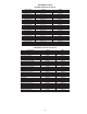
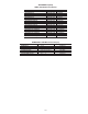
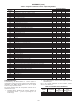
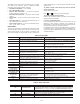
Table 4: Fault Codes
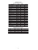
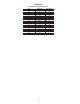
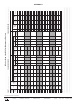
Table 5: Status Indication
FAULT CODE DESCRIPTION SOLUTION
AF
High Temperature Fault: Ambient temperature is too high;
Cooling fan has failed (if equipped).
Check cooling fan operation
CF
Control Fault: A blank EPM, or an EPM with
corrupted data has been installed.
Perform a factory reset using Parameter 48 — PROGRAM SELECTION.
See Programming Notes (Step 6).
cF
Incompatibility Fault: An EPM with an incompatible
parameter version has been installed.
Either remove the EPM or perform a factory reset
(Parameter 48) to change the parameter version of the
EPM to match the parameter version of the drive.
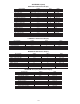
GF
Data Fault: User data and OEM defaults in the
EPM are corrupted.
Restore factory defaults by toggling P48 to another mode.
Then set P48 to desired mode to restore all defaults for that mode.
See configuration section (Step 2). If that does not work, replace EPM.
HF
High DC Bus Voltage Fault: Line voltage is too high;
Deceleration rate is too fast; Overhauling load.
Check line voltage — set P01 appropriately
JF
Serial Fault: The watchdog timer has timed out,
indicating that the serial link has been lost.
Check serial connection (computer)
Check settings for P15
Check settings in communication software to match P15
LF Low DC Bus Voltage Fault: Line voltage is too low. Check line voltage — set P01 appropriately
OF
Output Transistor Fault: Phase to phase or phase to ground
short circuit on the output; Failed output transistor; Boost
settings are too high; Acceleration rate is too fast.
Reduce boost or increase acceleration values.
If unsuccessful, replace drive.
PF
Current Overload Fault: VFD is undersized for the applica-
tion; Mechanical problem with the driven equipment.
Check line voltage — set P01 appropriately
Check for dirty coils
Check for motor bearing failure
SF
Single-phase Fault: Single-phase input power
has been applied to a three-phase drive.
Check input power phasing
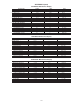
F1 EPM Fault: The EPM is missing or damaged.
F2-F9, Fo
Internal Faults: The control board has sensed a
problem.
Consult factory.
Drive display = ‘---’
even though drive
should be running
Start contact is not closed. Check auxiliary contact for proper operation and configuration. See configu-
ration section (Step 5).
Drive display = 8.0 Hz
even though fan should
be running faster
Control signal is at 4 mA Saturated condensing temperature is below setpoint
in ComfortLink controls.
VFD flashes 57
(or 47) and LCS
Speed signal lost. Drive will operate at 57 (or 47) Hz
until reset or loss of start command. Resetting
requires cycling start command (or power).
In stand-alone mode: In external control mode (30GXN,R)
check wiring from unit controls J8 for 4-20 mA signal.
Drive runs at 57 Hz in modes 5,6 and 47 Hz in modes 7,8.
VFD flashes
“LCS and - - -”
Start contact is not closed. Check auxiliary contact for proper operation and configuration. See configu-
ration section (Step 5).
LC Fault lockout — 3 or more unsuccessful starts View PSD: Fault History to determine.
FAULT CODE FAULT NAME DESCRIPTION
CL CURRENT LIMIT
The output has exceeded the CURRENT LIMIT setting (Parameter 25) and the drive
is reducing the output frequency to reduce the output current. If the drive remains in
CURRENT LIMIT for too long, it can trip into a CURRENT OVERLOAD fault (PF).
Er ERROR Invalid data has been entered.
GE GE
“GE” will be displayed if an attempt is made to change the OEM default settings
when the drive is operating in the OEM mode (see Parameter 48).
LC FAULT LOCKOUT Failed three restart attempts. Requires a manual reset.
SP START PENDING This is displayed during the first 15 second interval between restart attempts.