
Water Dispenser User Manual


Terminals TB2-11 and TB2-12 are provided for field in-
stallation of a chilled water (fluid) pump interlock (CWPI)
and a chilled water (fluid) flow switch (CWFS). These de-
vices are to be installed in series. Contacts must be rated for
day circuit applications capable of handling a 24-vac to
50 mA load.
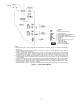
Accessory remote on-off switch can be wired into TB2-13
and TB2-14. To use this feature, remove the factory-installed
jumper and install the device in series. See Fig. 13 for re-
mote on-off, CWPI, and CWFS wiring. Contacts must be
rated for dry load application capable of handling a 24-vac
to 50 mA load.
Do not use interlocks or other safety device contacts
connected between TB2 terminals 13 and 14 as remote
on-off. Connection of safeties or other interlocks be-
tween these 2 terminals will result in an electrical
bypass if the REMOTE-OFF-LOCAL switch is in the
LOCAL position. If remote on-off unit control is re-
quired, a field-supplied relay must be installed in the
unit control box and wired as shown in Fig. 13. Failure
to wire the remote on-off as recommended will result in
tube freeze damage.
Terminals 2 and 3 of TB2 have been provided for a
field-supplied remote alarm (ALM). If an audible alarm is
installed, an alarm shutoff is also recommended. Contacts
are rated for 125 va at either 115 or 230 v control power. See
Fig. 13.
Terminals 4 and 5 of TB2 have been provided for a
field-supplied chilled water (fluid) pump relay (CWP). A
field-supplied power supply of appropriate voltage must be
provided. Contacts are rated for 125 va at either 115 or
230 v control power. See Fig. 13.
Terminals 1 and 6 of TB2 have been provided for a
field-supplied control relay for the remote condenser (30HXA)
or a condenser pump relay (30HXC). A field-supplied power
supply of appropriate voltage must be provided.
Step 5 — Install Accessories
ELECTRICAL — Several optional control accessories are
available to provide the following features:
• control transformer
• cooler pump/flow switch interlock
• cooler pump control
• expanded display panel
• remote alarm
• remote on-off
• pulldown control
• occupancy scheduling
• demand limit control
• temperature reset (from occupied space or outdoor-air
temperature)
• dual set point control
• condenser water sensors
• level II communications (CCN
[Carrier Comfort Network])
Refer to Start-Up and Operation literature and sepa-
rate accessory installation instructions for additional
information.
30HXA LOW-AMBIENT OPERATION — If outdoor
ambient operating temperatures below 60 F (15 C) are ex-
pected, refer to separate installation instructions for low-
ambient operation using accessory Motormastert III control.
MINIMUM LOAD ACCESSORY — If minimum load
accessory is required, use the appropriate package. Refer to
unit Price Pages or contact your local Carrier representative
for more details. For installation details, refer to separate in-
stallation instructions supplied with the accessory package.
MISCELLANEOUSACCESSORIES — For applications re-
quiring special accessories, the following packages are avail-
able: control power transformer, minimum load control, sound
reduction enclosure, external vibration isolation, expanded
display, Victaulic-type connections, temperature reset sen-
sor, and chilled fluid flow switch. Refer to individual acces-
sory installation instructions for installation details.
Step 6 — Leak Test Unit
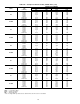
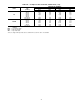
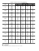
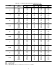
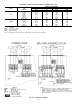
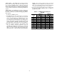
30HXC UNIT — These units are shipped from the factory
with a full charge of R-134a (See Tables 1A and 1B). Per-
form a leak test to ensure that leaks have not developed
during unit shipment. Dehydration of the system is not re-
quired unless the entire refrigerant charge has been lost. There
are a number of Swage-Lok fittings used on the refrigerant
piping. If a leak is detected at any of these fittings, tighten
outside nut
1
⁄
8
turn.
DO NOT OVERTIGHTEN THESE FITTINGS. Over-
tightening will result in the tube being crushed and will
cause a refrigerant system leak.
30HXA UNITS — These units are shipped with a holding
charge of R-134a. Leak test and dehydrate the complete sys-
tem (including both field and factory installed piping).
Step 7 — Refrigerant Charge
IMPORTANT: These units are designed for use with
R-134a only. DO NOT USE ANY OTHER refrig-
erant in these units without first consulting your
Carrier representative.
The liquid charging method is recommended for com-
plete charging or when additional charge is required.
When charging, circulate water through the condens-
er and cooler at all times to prevent freezing. Freezing
damage is considered abuse and may void the Carrier
warranty.
DO NOT OVERCHARGE system. Overcharging re-
sults in higher discharge pressure with higher cooling
fluid consumption, possible compressor damage, and higher
power consumption.
26