AIR CONDITIONER (MULTI TYPE) Installation Manual Indoor Unit Model name: High Wall Type MMK-AP0073H2UL MMK-AP0093H2UL MMK-AP0123H2UL MMK-AP0153H2UL MMK-AP0183H2UL MMK-AP0243H2UL Installation Manual Manuel d’installation 1 English 32 Français
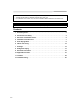
Please read this Installation Manual carefully before installing the Air Conditioner. • This Manual describes the installation method of the indoor unit. • For installation of the outdoor unit, refer to the Installation Manual attached to the outdoor unit. ADOPTION OF NEW REFRIGERANT This Air Conditioner uses R410A an environmentally friendly refrigerant. Contents 1 Accessory Parts . . . . . . . . . . . . . . . . . . . . . . . . . . . . . . . . . . . . . . . . . . . . . . . . . . .
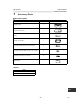
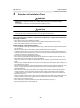
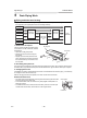
Installation Manual High Wall Type 1 Accessory Parts Accessory parts Part name Q’ty Installation plate 1 Wireless remote control 1 Battery 2 Remote control holder 1 Mounting screw Ø0.16” (4 mm) × 1.0” (25 mm) 6 Pan head wood screw Ø1/8” (3.1 mm) × 0.6” (16 mm) 2 Screw Ø0.16” (4 mm) × 0.
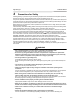
Installation Manual High Wall Type 2 Precautions for Safety Installing, starting up, and servicing air-conditioning equipment can be hazardous due to system pressures, electrical components, and equipment location (roofs, elevated structures, etc.). Only trained, qualified installers and service mechanics should install, start-up, and service this equipment. Untrained personnel can perform basic maintenance functions such as cleaning heat exchanger.
Installation Manual High Wall Type • If refrigerant gas has leaked during the installation work, ventilate the room immediately. If the leaked refrigerant gas comes in contact with fire, noxious gas may generate. • After the installation work, confirm that refrigerant gas does not leak. If refrigerant gas leaks into the room and flows near a fire source, such as a cooking range, noxious gas might generate.
Installation Manual High Wall Type 3 Selection of Installation Place WARNING • Install the air conditioner securely in a location where the base can sustain the weight adequately. If the strength is not enough, the unit may fall down resulting in injury. CAUTION • Do not install in a location where flammable gas leaks are possible. If the gas leak and accumulate around the unit, it may ignite and cause a fire.
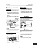
Installation Manual High Wall Type Before installing the wireless remote control 1.Remove the battery cover. 2.Insert 2 new batteries (R03 [AAA] type) following the (+) and (–) positions. 2.0” (50 mm) or more Installation diagram of Indoor and outdoor units *1 33.5 ” (85 0 mm ) or m ore Hook 6.
Installation Manual High Wall Type Wireless remote control ) m ’5 ” (5 ) 16 ’5 ” (7 m (Top view) Indoor unit 16 23’ 45° (5 m ) ° 45 75 ° Indoor unit (Side view) Reception range Reception Remote control range * 23’ (7 m) • A place where there are no obstacles such as a curtain that may block the signal from the indoor unit. • Do not install the remote control in a place exposed to direct sunlight or close to a heating source, such as a stove.
Installation Manual High Wall Type Cutting a hole and mounting installation plate When the installation plate is directly mounted on the wall Cutting a hole In case of installing the refrigerant pipes from the rear: 1. Decide the hole position for piping at 7.1” (180 mm) from the arrow mark (Ö) on the installation plate and drill a hole at a slight downward slant toward outdoor side. Pipe hole; dia.2.6” (65 mm): MMK-AP007 to 018 type Pipe hole; dia.3.1” (80 mm): MMK-AP024 type 1.
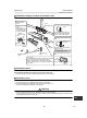
Installation Manual High Wall Type 5 Drain Piping Work Piping and drain hose forming * Apply heat-insulation for both refrigerant pipe and drain hose surely so that no dew generates inside of the equipment. (Use polyethylene foam for insulating material.) Rear right Rear left Bottom left Removing front panel Left Bottom right Changing drain hose Piping preparation Die-cutting front panel slit Right 1.
Installation Manual High Wall Type Remove the drains cap Clip the drain cap by needle-nose pliers and pull out. Fix the drains cap 1) Insert a 4 mm hexagonal wrench in a centre head. 4 mm 2) Firmly insert drains cap. No gap Do not apply lubricating oil (refrigerant machine oil) when inserting the drain cap. Application causes deterioration and drain leakage from the plug. Insert a 4 mm hexagon wrench CAUTION Firmly insert the drain hose and drain cap; otherwise, water may leak.
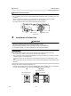
Installation Manual High Wall Type ▼ Bottom right or bottom left piping • After scribing slits of the front panel with a knife or a marking-off pin, cut them with a pair of nippers or an equivalent tool. Slit ▼ Left-hand connection with piping Bend the connecting pipe so that it is laid within 1.7” (43 mm) above the wall surface. If the connecting pipe is laid exceeding 1.7” (43 mm) above the wall surface, the indoor unit may unstably be set on the wall.
Installation Manual High Wall Type 6 7 Indoor Unit Fixing 1. Pass the pipe through the hole in the wall, and hook the indoor unit on the installation plate at the upper hooks. 2. Swing the indoor unit to right and left to confirm that it is firmly hooked up on the installation plate. 3. While pressing the indoor unit onto the wall, hook it at the lower part on the installation plate. Pull the indoor unit toward you to confirm that it is firmly hooked up on the installation plate. Drainage 1.
Installation Manual High Wall Type 8 Refrigerant Piping Refrigerant Piping Permissible Piping Length and Height Difference 1. Use copper pipe with 0.03” (0.8 mm) or more thickness. (In case pipe size is dia. 5/8” (15.9 mm), with 0.04” (1.0 mm) or more.) 2. Flare nut and flare works are also different from those of the conventional refrigerant. Take out the flare nut attached to the main unit of the air conditioner, and use it. They vary according to the outdoor unit.
Installation Manual High Wall Type Leak check test, evacuation and other procedure Tightening connection CAUTION • Do not apply excessive torque. Otherwise, the nut may crack depending on the conditions. For leak check test, evacuation, addition of refrigerant, and gas leak check, refer to the Installation Manual attached to the outdoor unit. REQUIREMENT Unit: ft•lbs (N•m) Outer dia. of copper pipe Tightening torque 1/4” (6.4 mm) 10 - 13 (14 - 18) 3/8” (9.5 mm) 24 - 31 (33 - 42) 1/2” (12.
Installation Manual High Wall Type Wireless remote control A-B selection NOTE To use 2 wireless remote controls for the respective air conditioners, when the 2 air conditioners are closely installed. Wireless remote control B setup • Repeat above step to reset wireless remote control to be A. • The wireless remote controls do not display “A”. • The factory default of the wireless remote controls is “A”. 1. Push button on the indoor unit to turn the air conditioner ON. 2.
Installation Manual High Wall Type 9 Electrical Connection REQUIREMENT WARNING 1. Use predefined wire and connect them certainly. Keep the connecting terminal free from external force. Improper wire connection or clamping may result in exothermic, fire or malfunction. 2. Connect ground wire. (grounding work) Incomplete grounding cause an electric shock. Do not connect ground wires to gas pipes, water pipes, lightning rods or ground wires for telephone wires. 3.
Installation Manual High Wall Type Power supply wire • Recommended wire diameter and wire length for power supply wire. Wire size: 2 × AWG12 Ground 1 × AWG12 or thicker Power supply wiring Up to 164’1” (50m) Electric characteristics MCA : Minimum Circuit Amps MOCP : Maximum Overcurrent Protection (Amps) MCA MOCP (A) (A) MMK-AP0073H2UL 0.3 15 MMK-AP0093H2UL 0.3 15 Model MMK-AP0123H2UL MMK-AP0153H2UL Power Supply 208/230V-1-60Hz Voltage Range (V) Min Max 187 253 0.3 15 0.
Installation Manual High Wall Type Wiring between indoor and outdoor units NOTE An outdoor unit connected with control wiring between indoor and outdoor units wire becomes automatically the header unit.
Installation Manual High Wall Type Wire Connection Terminal block for wired remote control/control wiring REQUIREMENT • Connect the wires matching the terminal numbers. Incorrect connection causes a trouble. • The low-voltage circuit is provided for the wired remote control and control wire. (Do not connect the high-voltage circuit) 1. Remove the air inlet grille. Open the air inlet grille upward and pull it toward you. 2. Remove the front panel. 3. Remove the terminal cover and the clamp base.
Installation Manual High Wall Type 5. Clamp the wires with the cord clamp. 6. Install the clamp base with a screw. 7. Remove the conduit cover. 12.Attach the conduit cover. 13.Attach the terminal cover, the front panel and the air inlet grille to the indoor unit. CAUTION Conduit cover Conduit hole (dia. 7/8” (22.2 mm)) Keep the wire length as shown in figure below when it is connected to the terminal block. 0.08” (2 mm) or less 8. Attach a conduit to the conduit cover with a lock nut. 9.
Installation Manual High Wall Type 10 Applicable Controls A wired remote control is necessary for this function. This function cannot be operate with a wireless remote control. REQUIREMENT • When this air conditioner is used for the first time, it takes approx. 5 minutes until the remote control becomes available after power-on. This is normal. It takes approx. 5 to 10 minutes until the remote control becomes available.
Installation Manual High Wall Type Procedure 2 Filter sign setting Each time button is pushed, indoor unit numbers in the control group change cyclically. Select the indoor unit to change settings for. The fan of the selected unit runs and the louvers start swinging. The indoor unit can be confirmed for which to change settings. According to the installation condition, the lighting time of the filter sign (Notification of filter cleaning) can be changed.
Installation Manual High Wall Type Adjustment of air direction 1. Using the remote control, change the up/ down air direction by moving the horizontal louver. 2. Adjust the right/left air direction by bending the vertical grille inside of the air outlet port with hands. REQUIREMENT Do not touch the horizontal louver directly with hands; otherwise a trouble may be caused. For handling of the horizontal louver, refer to “Owner’s Manual” attached to the indoor unit.
Installation Manual High Wall Type 11 Test Run ▼ In case of wired remote control Before test run • Before turning on the circuit breaker, carry out the following procedure. 1) By using 500V-megger, check that resistance of 1MΩ or more exists between the terminal block L1 to L2 and the ground (grounding). If resistance of less than 1MΩ is detected, do not run the unit. 2) Check the valve of the outdoor unit being opened fully.
Installation Manual High Wall Type ▼ In case of wireless remote control (Forced test operation is performed in a different way.) REQUIREMENT • For the operation procedure, be sure to follow the Owner’s Manual. • Finish the forced cooling operation in a short time because it applies excessive strength to the air conditioner. • A test operation of forced heating is unavailable. Perform a test operation by heating operation using the switches of the remote control.
Installation Manual High Wall Type 12 Troubleshooting A wired remote control is necessary for this function. This function cannot be operate with a wireless remote control. Procedure 2 Confirmation and check When an error occurred in the air conditioner, the check code and the indoor UNIT No. appear on the display part of the remote control. The check code is only displayed during the operation.
Installation Manual High Wall Type Check codes and parts to be checked Check method On the remote control (Wired remote control, Central control remote control) and the interface P.C. board of the outdoor unit (I/F), a check display LCD (Remote control) or 7-segment display (on the outdoor interface P.C. board) to display the operation is provided. Therefore the operation status can be known.
Installation Manual High Wall Type Check code Wireless remote control Wired remote control display Outdoor 7-segment display E28 E28 Detected outdoor unit number A3-IPDU 01 E31 07 c c c c c c c c c c c c 0C 0D c 0E 0F I/F c c c 0A 0B IPDU communication error Fan IPDU c 08 09 I/F c 06 E31 3 Follower outdoor unit error c c 04 05 Judging device c 02 03 2 Check code name Operation Timer Ready Flash Auxiliary code 1 Sensor block display of receiving unit c c c
Installation Manual High Wall Type Check code Wired remote control display Wireless remote control Outdoor 7-segment display Sensor block display of receiving unit Check code name Judging device Operation Timer Ready Flash Auxiliary code H05 H05 — TD1 miswiring I/F H06 H06 — Low pressure protective operation I/F H07 H07 — Oil level down detective protection I/F H08 01: TK1 sensor error 02: TK2 sensor error H08 03: TK3 sensor error 04: TK4 sensor error Oil level detective temp sens
Installation Manual High Wall Type Check code Wired remote control display P04 Wireless remote control Outdoor 7-segment display Auxiliary code Sensor block display of receiving unit Judging device Operation Timer Ready Flash 01: Comp. 1 side P04 02: Comp. 2 side 03: Comp. 3 side ALT High-pressure SW system operation IPDU Phase loss error/interruption of power supply 00: Detected phase loss P05 Check code name P05 01: Comp. 1 side 02: Comp. 2 side 03: Comp.
Installation Manual High Wall Type WARNINGS ON REFRIGERANT LEAKAGE Check of Concentration Limit The room in which the air conditioner is to be installed requires a design that in the event of refrigerant gas leaking out, its concentration will not exceed a set limit. The refrigerant R410A which is used in the air conditioner is safe, without the toxicity or combustibility of ammonia, and is not restricted by laws to be imposed which protect the ozone layer.
Confirmation of Indoor Unit Setup Prior to delivery to the customer, check the address and setup of the indoor unit, which has been installed in this time and fill the check sheet (Table below). Data of four units can be entered in this check sheet. Copy this sheet according to the No. of the indoor units. If the installed system is a group control system, use this sheet by entering each line system into each installation manual attached to the other indoor units.