
Installation manual

High Wall Type
Installation Manual
–6–
EN
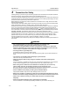
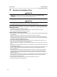
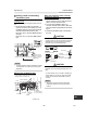
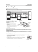
Installation diagram of Indoor and outdoor units
Installation space
The indoor unit shall be installed so that its top surface comes at a height of 6’7” (2 m) or more.
Also it must be avoided to put anything on top of the indoor unit.
*1 Provide a space as shown for service clearance for the cross flow fan.
Installation place
• A place which provides the spaces around the indoor unit as shown in the above diagram.
• A place where there is no obstacle near the air inlet and outlet.
• A place that allows easy installation of the piping to the outdoor unit.
• A place which allows the front panel to be opened.
CAUTION
• Direct sunlight to the indoor unit’ s wireless receiver should be avoided.
• The microprocessor in the indoor unit should not be too close to RF (Radio Frequency) noise sources.
(For details, see the owner’ s manual.)
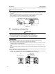
A
CL
For the rear left and left piping
Wall
Insert the cushion between the
indoor unit and wall, and tilt the
indoor unit for better operation.
Do not allow the drain hose to get
slack.
Cut the piping hole
sloped slightly.
Make sure to run the drain hose
sloped downward.
The auxiliary piping can be
connected to the left, rear left, rear
right, right, bottom right or bottom
left.
Right
Rear right
Bottom right
Bottom left
Rear left
2.0” (50 mm) or more
6
.
7
”
(
1
7
0
m
m
)
o
r
m
o
r
e
3
3
.
5
”
(
8
5
0
m
m
)
o
r
m
o
r
e
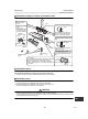
Hook
Installation plate
Hook
Connecting
pipe
A
i
r
f
i
l
t
e
r
(
A
tt
a
c
h
t
o
t
h
e
f
r
o
n
t
p
a
n
e
l
.
)
Remote control
holder
Pan head wood
screw
Batteries
Wireless remote
control
Before installing the
wireless remote
control
1.Remove the battery
cover.
2.Insert 2 new
batteries (R03 [AAA]
type) following the
(+) and (–) positions.
Wireless
remote control
Cover
Batteries
Heat
insulator
*
1
Left
* CAUTION
Connecting pipe cannot be connected to the right side
of the indoor unit when conduit pipe is used.
When connecting pipe is connected on the left or
bottom of the indoor unit, connect the conduit pipe on
other side.
6-EN