R Diesel Engine WORKSHOP MANUAL for V2203-DI (26--00128) Tier 4i 62--11362 Rev --
WORKSHOP MANUAL DIESEL ENGINE V2203-DI (26-00118) Tier 4i
TABLE OF CONTENTS PARAGRAPH NUMBER Page SAFETY PRECAUTIONS . . . . . . . . . . . . . . . . . . . . . . . . . . . . . . . . . . . . . . . . . . . . . . . . . . . . . . . . . . . . . . . . . . . iv SPECIFIC WARNING AND CAUTION STATEMENTS . . . . . . . . . . . . . . . . . . . . . . . . . . . . . . . . . . . . . . . . . . iv General . . . . . . . . . . . . . . . . . . . . . . . . . . . . . . . . . . . . . . . . . . . . . . . . . . . . . . . . . . . . . . . . . . . . . . . . . . . . . . . . . . . . . . 1--1 1.
Page PARAGRAPH NUMBER ENGINE BODY . . . . . . . . . . . . . . . . . . . . . . . . . . . . . . . . . . . . . . . . . . . . . . . . . . . . . . . . . . . . . . . . . . . . . . . . . . . . . . . 2--1 2.1 CHECKING AND ADJUSTING . . . . . . . . . . . . . . . . . . . . . . . . . . . . . . . . . . . . . . . . . . . . . . . . . . . . . . . . . 2--1 2.1.1 Compression Pressure . . . . . . . . . . . . . . . . . . . . . . . . . . . . . . . . . . . . . . . . . . . . . . . . . . . . . . . . . . . . . 2--1 2.1.
Page PARAGRAPH NUMBER FUEL SYSTEM . . . . . . . . . . . . . . . . . . . . . . . . . . . . . . . . . . . . . . . . . . . . . . . . . . . . . . . . . . . . . . . . . . . . . . . . . . . . . . . 5--1 5.1 CHECKING AND ADJUSTING . . . . . . . . . . . . . . . . . . . . . . . . . . . . . . . . . . . . . . . . . . . . . . . . . . . . . . . . . 5--1 5.1.1 Injection Timing . . . . . . . . . . . . . . . . . . . . . . . . . . . . . . . . . . . . . . . . . . . . . . . . . . . . . . . . . . . . . . . . . . . 5--1 5.1.
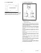
SAFETY SAFETY PRECAUTIONS cap must be removed, do so very slowly in order to release the pressure without spray. Your Carrier Transicold unit has been designed with the safety of the operator in mind. During normal operation, all moving parts are fully enclosed to help prevent injury. During all pre-trip inspections, daily inspections, and problem troubleshooting, you may be exposed to moving parts.
The statements listed below are specifically applicable to this unit and appear elsewhere in this manual. These recommended precautions must be understood and applied during operation and maintenance of the equipment covered herein. WARNING Beware of moving V--belt and belt driven components WARNING When removing the radiator cap, wait at least ten minutes after the engine has stopped and cooled down. Otherwise, hot water may discharge from the radiator, scalding anyone nearby.
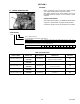
SECTION 1 General When contacting Carrier Transicold, always specify your engine model number and serial number. The engine model and its serial number need to be identified before the engine can be serviced or parts replaced. 1.1 ENGINE IDENTIFICATION S/N Engine Serial Number The engine serial number is an identified number for the engine. It is marked after the engine model number.
1.2 ENGINE SPECIFICATIONS Table 1-2. Specification Chart MODEL NUMBER 26--00128--00 TYPE 26--00128--01 26--00128--02 26--00128--04 NUMBER OF CYLINDERS BORE X STROKE 4 mm X mm (in. X in.) TOTAL DISPLACEMENT MAXIMUM SPEED RPM IDLING SPEED RPM 83 X 102.4 (3.27 X 4.03) cm3 (cu.in.) BRAKE HORSEPOWER SAE Intermittent HP kW (HP) / RPM 2216 (135.2) 23.65 (31.7) / 1700 23.87 (32.0) / 1800 26.85 (36.0) / 2200 23.87 (32.
1.3 CYLINDER NUMBER 1.4 GENERAL PRECAUTIONS 1 The cylinder numbers of V2203--DI series engine are designated as shown above. The sequence of cylinder numbers is given as No.1, No. 2, No. 3, and No. 4 starting from the gear case end of the engine. 2 2 3 3 1. Grease A External Snap Ring 2. Force B Internal Snap Ring 3. Place the Sharp Edge against the Direction of Force During disassembly, carefully arrange removed parts in a clean area to prevent confusion later.
1.5 TORQUE SPECIFICATIONS Screws, bolts and nuts must be tightened to the specified torque using a torque wrench. Several screws, bolts and nuts such as those used on the cylinder head must be tightened in the proper sequence and at the proper torque. 1.5.1 Torque Specifications For Special Use Screws, Bolts and Nuts In removing and applying the screws, bolts and nuts marked with “*”, a pneumatic wrench or similar tool, if employed, must be used with care.
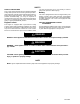
1.6 TROUBLESHOOTING Symptom Engine Does Not Start Probable Cause Solution Replenish fuel Vent Air Change fuel and repair or replace fuel system Clean Clean or change Use specified fuel or engine oil Use specified fuel Adjust Replace Replace Repair or Replace Reference -1.8.4 1.8.4 Replace head gasket, tighten cylinder head screw, glow plug and nozzle holder Correct or replace timing gear Replace Adjust ----- 2.3.3.d 1.8.
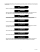
1.6 TROUBLESHOOTING (Continued) Symptom Excessive Lubricant Oil Consumption Fuel Mixed into Lubricant Oil Water Mixed into Lubricant Oil Low Oil Pressure High Oil Pressure Engine Overheated Low Battery Charge Probable Cause Piston ring’s gap facing the same direction Oil ring worn or stuck Piston ring groove worn Valve stem and valve guide worn Crankshaft bearing, and crank pin bearing worn Oil leaking due to defective seals or packing Injection pump’s plunger worn Reference 2.2.6.a 2.3.3.d 2.3.3.
1.7 SERVICING SPECIFICATIONS 1.7.1 Engine Body Item Cylinder Head Surface Factory Specification -- Flatness Compression Pressure 2.95 to 3.23 MPa/ 290 rpm 30 to 33 kgf/cm2 290 rpm 427 to 469 psi/ 290 rpm Allowable Limit 0.05 mm/500mm 0.0020 in./ 19.69 in. 2.35 MPa/ 290 rpm 24kgf/cm2 290 rpm 341 psi/ 290 rpm -0.60 to 0.70 mm 0.0236 to 0.0276 in. 0.18 to 0.22 mm 0.0071 to 0.0086 in. 2.12 mm 0.0835 in. 10% or less -- 2.12 mm 0.0835 in.
1.7.1 Engine Body (Continued) Item Valve Spring Free Length Setting Load/ Setting Length Tilt Rocker Arm Shaft to Rocker Arm Factory Specification 41.7 to 42.2 mm 1.65 to 1.66 in. Allowable Limit 41.2 mm 1.62 in. 118 N / 35.0 mm 12.0 kgf / 35.0 mm 26.5 lbs. / 1.38 in. 100.0N / 35.0 mm 10.2kgf / 35.0 mm 22.5lbs /1.38 in -- 1.0 mm 0.039 in. 1.0 mm 0.039 in. Clearance 0.016 to 0.045 mm 0.00063 to 0.0017 in. Rocker Shaft O.D. 13.973 to 13.984 mm 0.55012 to 0.55055 in. -- Rocker Arm I.D. 14.
1.7.1 Engine Body (Continued) Item Camshaft Side Clearance Camshaft Alignment Cam (Lobe) Height (Intake) 33.27 mm 1.310 in. Allowable Limit 0.3 mm 0.012 In. 0.01 mm 0.0004 in. 33.22 mm 1.308 in. Height (Exhaust) 33.47 mm 1.318 in. 33.42 1.316 in. 0.050 to 0.091 mm 0.0020 to 0.0035 in. 0.15 mm 0.00059 in. Camshaft Journal to Cylinder Block Bore Clearance Factory Specification 0.07 to 0.22 mm 0.0028 to 0.0086 in. -- Camshaft Journal O.D. 39.934 to 39.950 mm 1.5722 to 1.5728 in.
1.7.1 Engine Body (Continued) Item Crankshaft Journal to Crankshaft Bearing2 Oil Clearance Factory Specification 0.040 to 0.104 mm 0.00158 to 0.00409 in. Allowable Limit 0.2 mm 0.0079 in. Crankshaft Journal O.D. 59.921 to 59.940 mm 2.3591 to 2.3598 in. -- Crankshaft Bearing2 I.D. 59.980 to 60.025 mm 2.3615 to 2.3631 in. 0.025 to 0.087 mm 0.00099 to 0.0034 in. -- Crankpin to Crankpin Bearing Oil Clearance 0.2 mm 0.0079 in. Crankpin O.D. 46.959 to 46.975 mm 1.8488 to 1.8494 in.
1.7.2 Lubricating System Item Engine Oil Pressure At Idle Speed At Rated Speed Engine Oil Pressure Switch Working Pressure Inner Rotor to Outer Rotor Clearance Outer Rotor to Pump Body Clearance Inner Rotor to Cover Clearance Factory Specification More Than 98 kPa 1.0 kgf/cm2 14 psi Allowable Limit 50 kPa 0.5 kgf/cm2 7 psi 300 to 440 kPa 3.0 to 4.5kgf/cm2 43 to 64 psi 50 kPa 0.5kgf/cm2 7 psi 0.03 to 0.14 mm 0.0012 to 0.0055 in. 0.11 to 0.19 mm 0.0044 to 0.0074 in. 0.105 to 0.150 mm 0.
1.7.5 Electrical System Item Factory Specification Allowable Limit Starter Commutator O.D. 32.0 mm 1.26 in. 31.4 mm 1.24 in. Mica Undercut 0.50 mm 0.020 in. 0.20 mm 0.0079 in. Brush Length 0.18 mm 0.709 in. 11.0 mm 0.433 in. Infinity Approx. 0.
1.8 CHECK AND MAINTENANCE NOTE 1.8.1 Checking Engine Oil Level When adding coolant to the system, air must be vented from the engine coolant passages. Venting air can be accomplished by jiggling the upper and lower radiator hoses. Be sure to close the radiator cap securely. If the cap is loose or improperly closed, coolant may leak out and the engine could overheat. Do not use an antifreeze and scale inhibitor at the same time. Never mix different types or brands of coolants. 1. Level the engine. 2.
NOTE When changing to a different oil manufacturer or viscosity, be sure to remove all of the old oil completely. Never mix different types of oil. Use only API classification CG--4 or better oils. Use the proper SAE engine oil according to the ambient temperatures. Above 25°C (77°F).............SAE 30 or 10W--30 10W--40 0° to 25°C (32° to 77°F)......SAE 20 or 10W--30 10W--40 Below 0°C (32°F)............SAE 10W or 10W--30 1.8.4 Bleeding Fuel System 1.
1.8.7 Valve Clearance NOTE Valve clearance must be checked and adjusted when the engine is cold. 1. Remove the valve cover. 2. Align the “1TC” mark line (3) on the flywheel and projection (2) on the housing so that the Number 1 piston comes to compression or overlap top dead center (TDC). 3. Check the following valve clearance (1) marked with “*” using a feeler guage. Valve Clearance Factory Specification 0.18 to 0.22 mm 0.0071 to 0.0086 in. 4.
1.9 SPECIAL TOOLS Additional tools may be found in the Carrier Transicold Performance Parts Service Tool Catalog Number 62--03213. 1.9.1 Diesel Engine Compression Tester (Glow Plug) Part No. 07--00179--01 (Assembly) Application: Use to measure diesel engine compression and diagnosis for major overhaul. 1.9.2 Adapter, Injector To Tester Hose Part No. 07--00484--00 Application: Accessory for 07--00179--01 1.9.3 Tester Injector Nozzle Part No.
1.9 SPECIAL TOOLS (Continued) 1.9.6 Oil Pressure Tester Code No. 07916--32032 Application: Use to measure lubricating oil pressure. 1. 2. 3. 4. Guage Adapter 2 Cable Adapter 3 5. 6. 7. 8. Threaded Joint Adapter 4 Adaptor 1 Adaptor 3 1.9.7 Auxiliary Socket For Fixing Crankshaft Sleeve Code No. 07916--32091 Application: Use to fix the crankshaft sleeve of the diesel engine. 1.9.8 Gauge, Belt Tension Part No. 07--00203--00 Application: Used to adjust belt tension of all cogged V--belts. 1.9.
1.9 SPECIAL TOOLS (Continued) The following are drawings for special tools that may need to be fabricated. 1.9.13 Valve Guide Replacing Tool Application: Use to press out and press fit the valve guide. A 20 mm dia. (0.79 in. dia.) B 11.7 to 11.9 mm dia. (0.460 to 0.468 in. dia.) C 6.5 to 6.6 mm dia. (0.256 to 0.259 in. dia.) D 225 mm (8.86 in.) E 70 mm (2.76 in.) F 45 mm (1.77 in.) G 25 mm (0.98 in.) H 5 mm (0.197 in.) I 6.7 to 7.0 mm dia. (0.263 to 0.275 in. dia.) J 20 mm dia. (0.787 in. dia.) K 12.
1.9 SPECIAL TOOLS (Continued) 1.9.16 Crankshaft Bearing 1 Replacing Tool Application: Use to press out and press fit the crankshaft bearing No. 1 1. Extracting tool 130 mm (5.31 in.) A B 72 mm (2.83 in.) C R40 mm (R1.57 in.) D 10 mm (0.39 in.) E 20 mm (0.79 in.) F 20 mm dia. (0.79 in. dia.) G 64.8 to 64.9 mm dia. (2.551 to 2.555 in. dia.) H 59.8 to 59.9 mm dia. (2.354 to 2.358 in. dia.) 2. Extracting tool A 130 mm (5.31 in.) B 72 mm (2.83 in.) C R40 mm (R1.57 in.) D 10 mm (0.39 in.) E 20 mm (0.79 in.
SECTION 2 ENGINE BODY 2.1 CHECKING AND ADJUSTING 2.1.1 Compression Pressure 2.1.2 Top Clearance 1. Run the engine until it is warmed up. 2. Stop the engine and disconnect the 2P connector from the stop solenoid to prevent fuel delivery to the engine. 3. Remove the the air cleaner, the muffler and all the injection nozzles. 4. Install a compression tester with the adapter in one of the nozzle hole. 5. While cranking the engine with the starter measure the compression pressure. 6.
2.2 DISASSEMBLE AND REASSEMBLY 2.2.1 Draining Coolant And Engine Oil 2.2.2 External Components Air Cleaner, Muffler and Others 1. Remove the air cleaner and muffler. 2. Remove the fan, fan belt, alternator and starter. When Reassembling CAUTION Never remove the radiator cap until coolant temperature is below its boiling point. Loosen the cap slightly to the first stop to relieve any excess pressure before removing the cap completely. NOTE Check to see that there are no cracks on the belt surface. 1.
2.2.3 Cylinder Head And Valves 2.2.3.a Valve Cover 1. Remove the breather hose (2). 2. Remove the valve cover bolts (1). 3. Remove the valve cover (3). When Reassembling Check to see that the valve cover gasket (4) is in good condition and in place. Tightening Torque Valve Cover Bolts 1. Valve Cover Bolt 2. Breather Hose 3. Valve Cover 6.87 to 11.2 N.m 0.7 to 1.15 kgf.m 5.07 to 8.31 ft--lbs 4. Valve Cover Gasket 5. Breather Valve 6. Plate 2.2.3.b Injection Pipes 1.
2.2.3 Cylinder Head And Valves (Continued) 2.2.3.c Nozzle Holder Assembly 1. Remove the overflow pipe assembly. 2. Remove the nozzle holder assemblies (1). When Reassembling Replace the copper gasket with a new one. Tightening Torque Nozzle Holder Assembly 26 to 29 N.m 2.6 to 3.0 kgf.m 19 to 21 ft--lbs Overflow Pipe Assembly Retaining Bolt 9.81 to 11.2 N.m 1.00 to 1.15 kgf.m 7.24 to 8.31 ft--lbs 2.2.3.d Rocker Arm and Push Rod 1. Remove the rocker arm bracket mounting bolts (1). 2.
2.2.3 Cylinder Head And Valves (Continued) 14 6 18 10 17 9 13 2 3 5 11 7 1 15 8 4 2.2.3.e Cylinder Head 1. Loosen the hose clamp (1), and remove the water return pipe (2). 2. Remove the cylinder head bolts in the order of (18) to (1). 3. Lift up the cylinder head and remove. 4. Remove the cylinder head gasket (3). When Reassembling Replace the cylinder head gasket (3) with a new one. Apply oil to, then re--install the cylinder head bolts.
2.2.4 Injection Pump and Gear Case 2.2.4.a Injection Pump 1. Remove the fuel speed solenoid (2) and hi--idling body (3). 2. Remove the engine stop lever (5) and stop solenoid guide (6). 3. Remove the fuel injection pump assembly (7). NOTE Remove the injection pump assembly (7) after removing the fuel speed solenoid (2) and hi--idling body (3), engine stop lever (5) and stop solenoid guide (6).
2.2.4 Injection Pump and Gear Case (Continued) 2.2.4.b Governor Springs and Speed Control Plate NOTE Specific Tool (1): A 1.2mm (.050 inch) diameter wire with a total length of 200mm (8 inch) with the tip bent into a hook as depicted in the illustration is required to hang the governor springs. 1. Remove the injection pump cover. 2. Remove the speed control plate (7) mounting nuts (3) and bolts (4). 3. Using the Specific Tool (1), undo the the large governor spring (5) from the fork lever (2). 4.
2.2.4 Injection Pump and Gear Case (Continued) 2.2.4.b Governor Springs and Speed Control Plate (Continued) When Reassembling NOTE A length of string passed thru the governor spring can be used to retrieve the spring if it unhooks from both the specific tool and the speed control plate. Begin reassembly by inserting the specific tool (1) thru the injection pump cover opening thru to the speed control plate opening. 1.
2.2.4 Injection Pump and Gear Case (Continued) 2.2.4.c Fan Drive Pulley 1. Lock the flywheel using the flywheel stopper 2. Remove the fan drive pulley mounting nut (1) using the 46 mm deep socket wrench (3). 3. Remove the fan drive pulley (2) with a gear puller (4). 4. Remove the feather key. When Reassembling Apply grease to the splines of the coupling. Tightening Torque 1. Nut 2. Fan Drive Pulley 3. 46 mm Deep Socket wrench 4. Gear Puller Drive Pulley Mounting Nut 138 to 156 N.m 14.0 to 16.0 kgf.
2.2.4 Injection Pump and Gear Case (Continued) 2.2.4.e Crankshaft Oil Slinger 1. Remove the crankshaft collar (1). 2. Remove the O--ring (2). 3. Remove the crankshaft oil slinger (3). When Reassembling Insert the crankshaft collar (1) after installing the gear case to the crankcase. 1. Crankshaft Collar 2. O--ring 3. Crankshaft Oil Slinger 2.2.4.f Idle Gear 1. Detach the external snap ring. 2. Remove the idle gear collar. 3. Remove the idle gear (2).
2.2.4 Injection Pump and Gear Case (Continued) 2.2.4.i Fuel Camshaft And Fork Lever Assembly 1. Detach the fuel camshaft stopper (1). 2. Remove the three fork lever holder mounting screws (2). 3. Remove the fuel camshaft assembly (5), (6) and fork lever assembly (3), (4), and (7) at the same time. When Reassembling After installation, check to see that the fork levers 1 (3) and 2 (4) are fixed to the fork lever shaft, and that they can turn smoothly in the holder (7). 1. Fuel Camshaft Stopper 2.
2.2.5 Oil Pan and Oil Strainer 2.2.5.a Oil Pan and Oil Strainer 1. Remove the oil pan cover (4). 2. Remove the oil pan mounting bolts (1). 3. Remove the oil pan (2) by lightly tapping the rim of the pan with a wooden hammer. 4. Remove the old gaskets (3) and (7). 5. Remove the oil strainer (6) and O--ring (5). When Reassembling Check to see that the oil filter strainer (6) is clean. Visually check the O--ring (5), apply engine oil and install it to the pick--up tube.
2.2.6 Piston and Connecting Rod 2.2.6.a Pistons 1. Completely remove the carbon ridge (1) at the top of the cylinder walls. 2. Remove the connecting rod cap (3). 3. Turn the flywheel and bring the piston to top dead center. 4. Push the piston out by lightly tapping the connecting rod from the bottom of the crankcase with the grip of a hammer. 5. Repeat the procedure for the other three cylinders. When Reassembling Liberally coat the piston and piston rings with engine oil.
2.2.6 Piston and Connecting Rod (Continued) 2.2.6.b Piston Ring and Connecting Rod 1. Remove the piston rings (1), (2), (3). 2. Remove the piston pin (8) and then seperate the connecting rod (6) from the piston (5). 7 NOTE 8 Mark both the connecting rod and piston so that if they are to be re--used that the original combination of parts will go back together. Do not interchange used parts.
2.2.7 Crankshaft 2.2.7.a Flywheel 1. Prevent the flywheel (1) from rotating. 2. Remove two flywheel bolts (2). NOTE The use of air tools to remove the flywheel bolts may damage the threads in the crankshaft. 1. Flywheel 2. Flywheel Bolt 3. Install two flywheel guide bolts (3). 4. Remove all of the flywheel bolts (2). 5. Remove the flywheel (1) slowly along the flywheel guide bolts (3). When Reassembling Install two flywheel guide bolts (3).
2.2.7 Crankshaft (Continued) 2.2.7.c Crankshaft Assembly Removal NOTE Before disassembling, check the side clearance of the crankshaft. Check it during reassembly. 1. Remove the three main bearing case bolts (1). 2. Pull out the crankshaft assembly (2), being careful not to damage the crankcase bearings (3). 3. While pulling the crankshaft assembly (2) out, use care to align each of the crank pins (5) (left or right) to clear the crankcase relief (a).
2.2.7 Crankshaft (Continued) 2.2.7.d Main Bearing Case Assembly 1. Remove the two main bearing case bolts (7), and remove the main bearing case assembly being careful with the thrust bearing and crankshaft bearing. 2. Remove the remaining main bearing cases as above. When Reassembling Clean the oil passages in the main bearing case. Apply clean engine oil to the bearings. Install the main bearing case assemblies in their original locations. The diameters of the main bearing cases vary.
2.3 SERVICING 2.3.1 Cylinder Head And Valves 2.3.1.a Cylinder Head Surface Flatness 1. Clean the cylinder head surface. 2. Place a straightedge on the cylinder head surface, in six locations as depicted in the drawing. 3. Measure any clearance between the straightedge and cylinder head with a feeler gauge. 4. If the measurement exceeds the allowable limit, resurface or replace the head. NOTE Check the valve recessing after after resurfacing the head.
2.3.1 Cylinder Head And Valves (Continued) 2.3.1.c Valve Recessing 1. Clean the cylinder head surface (1), valve face and valve seat. 2. Insert the valve into the head, making certain that the valve is fully seated. 3. Measure the valve recessing with a depth gauge. 4. If the measurement exceeds the allowable limit, replace the valve. 1. Cylinder Head Surface (A) Recess (B) Protrusion 5. If the measurement still exceeds the allowable limit, replace the cylinder head.
2.3.1 Cylinder Head And Valves (Continued) 2.3.1.e Replacing Valve Guide (A) (When removing) 1. Press out the used valve guide using a valve guide replacing tool. (B) (When installing) 1. Clean a new valve guide and valve guide bore, then apply oil to them. 2. Press in a new valve guide using a valve guide replacing tool. 3. Ream the I.D. of the valve guide to the specified dimension (precisely). Valve Guide I.D. Intake & Exhaust (A) When Removing Factory Specification 8.015 to 8.030 mm 0.3156 to 0.
2.3.1 Cylinder Head And Valves (Continued) 2.3.1.g Correcting Valve and Valve Seat NOTE Before correcting the valve seat, make certain that the valve and valve guide are within factory specifications. After correcting the valve seat, be sure to check the valve recessing. (A) Correcting the Valve 1. Correct the valve with a valve grinder. Valve Face Angle a Factory Specification IN. 0.79 rad / 45° EX. 0.79 rad / 45° b (B) Correcting the Valve Seat 1. Slightly correct the valve seat surface with a 1.
2.3.1 Cylinder Head And Valves (Continued) 2.3.1.i Free Length and Tilt of Valve Spring 1. Measure the free length A of the valve spring with vernier calipers. If the measurement is less than the allowable limit, replace the spring. 2. Put the valve spring on a surface plate, place a square on the side of the valve spring. 3. Check to see if the entire side is in contact with the square. Rotate the spring and measure for maximum tilt B. Check the entire surface of the valve spring for defects.
2.3.1 Cylinder Head And Valves (Continued) 2.3.1.m Oil Clearance Between Tappet and Tappet Guide Bore 1. Measure the tappet O.D. with a micrometer. 2. Measure the I.D. of the tappet guide bore with a cylinder gauge and calculate the clearance. 3. If the measurement exceeds the allowable limit, or the tappet is damaged, replace the tappet. Factory Specification 0.020 to 0.062 mm 0.00079 to 0.00244 in. Allowable Limit 0.07 mm 0.003 in. Tappet O.D. Factory Specification 23.959 to 23.980 mm 0.94327 to 0.
2.3.2 Timing Gears, Camshaft and Fuel Camshaft (Continued) 2.3.2.c Camshaft Side Clearance 1. Set a dial indicator with its tip on the camshaft. 2. Move the camshaft gear front to rear to measure the side clearance. 3. If the measurement exceeds the allowable limit, replace the camshaft stopper. Camshaft Side Clearance Factory Specification 0.07 to 0.22 mm 0.0028 to 0.0087 in. Allowable Limit 0.30 mm 0.0118 in. 2.3.2.d Idle Gear Shaft and Idle Gear Bushing Clearance 1. Measure the idle gear shaft O.D.
2.3.2 Timing Gears, Camshaft and Fuel Camshaft (Continued) 2.3.2.f Camshaft Alignment 1. Support the camshaft with V blocks on a surface plate at both end journals. 2. Set a dial indicator with its tip on the intermediate journal. 3. Rotate the camshaft and measure for run--out. 4. If the measurement exceeds the allowable limit, replace the camshaft. Camshaft Run--out Allowable Limit 0.1 mm 0.0004 in. 2.3.2.g Cam Height 1. Measure the cam lobe at its largest O.D. with an outside micrometer. 2.
2.3.3 Piston and Connecting Rod 2.3.3.a Piston Pin Bore I.D. 1. Measure the piston pin bore I.D. in both the horizontal and vertical directions with a cylinder gauge. 2. If the measurement exceeds the allowable limit, replace the piston. Piston Pin Bore I.D. Factory Specification 25.000 to 25.013 mm 0.98426 to 0.98476 in. Allowable Limit 25.05 mm 0.9862 in. 2.3.3.b Piston Pin and Bushing Clearance 1. Measure the piston pin O.D. with an outside micrometer. 2.
2.3.3 Piston and Connecting Rod (Continued) 2.3.3.d Piston Ring Gap 1. Insert the piston ring into the lower part of the cylinder (the least worn section). Use the piston to square the ring in the cylinder. 2. Measure the ring gap with a feeler gauge. 3. If the gap exceeds the allowable limit, replace the ring. Top Ring (Keystone Type) Second Ring Oil Control Ring Factory Specification 0.20 to 0.35 mm 0.0079 to 0.013 in. Allowable Limit 1.25 mm / 0.0492 in. Factory Specification 0.40 to 0.55 mm 0.
2.3.4 Crankshaft 2.3.4.a Crankshaft End Clearance 1. Push on the end of the crankshaft to seat it toward the flywheel end of the engine block. 2. Attach, then zero a dial indicator on the forward end of the crankshaft. 3. Measure the end play by pulling the crankshaft forward. 4. If the measurement exceeds the allowable limit replace the thrustwashers. Crankshaft Side Clearance A B Factory Specification 0.15 to 0.31 mm 0.0059 to 0.012 in. Allowable Limit 0.5 mm 0.02 in.
2.3.4 Crankshaft (Continued) 2.3.4.c Crankpin to Connecting Rod Bearing Clearance 1. Clean the crankpin and the connecting rod bearing. 2. Put a strip of plastigage on the center of the crankpin in each direction as shown in the figure. 3. Install the connecting rod cap and tighten the bolts to the specification. (Refer to 2.2.6.a) 4. Remove the cap again 5. Measure the amount of the flattening with the scale to get the clearance. 6.
2.3.4 Crankshaft (Continued) 2.3.4.d Crankshaft Journal to Crankshaft Bearing #1 Clearance 1. Measure the O.D. of the crankshaft journal with an outside micrometer. 2. Measure the I.D. of crankshaft bearing #1 with an inside micrometer and calculate clearance. 3. If the clearance exceeds the allowable limit, replace crankshaft bearing #1. 4. If the allowable limit is not attainable with a standard size bearing, install an undersize bearing by referring to the table below.
2.3.4 Crankshaft (Continued) 2.3.4.f Crankshaft Journal to Crankshaft Bearing #2 Clearance 1. Put a strip of plastigage on the center of the crankshaft journal. 2. Install the bearing case and tighten the bolts to specification. 3. Remove the bearing case again. 4. Measure the amount of the flattening with the scale to get the clearance. 5. If the measurement exceeds the allowable limit replace crankshaft bearing #2. 6.
2.3.4 Crankshaft (Continued) 2.3.4.g Replacing Crankshaft Sleeve 1. Remove the crankshaft sleeve (3) using a special-use puller set. 2. Set the sleeve guide (2) to the crankshaft (5). 3. Set the stopper (1) to the crankshaft (5) as shown in the figure. 4. Heat the new sleeve to a temperature between 150 to 200°C (302 to 392°F), and fix the sleeve on the crankshaft (5) as shown in the figure. 5. Press fit the sleeve using the auxiliary socket for pushing (4).
2.3.5 Cylinder 2.3.5.a Cylinder Wear 1. Measure the I.D. of the cylinder at the six positions (see figure with a cylinder gauge to find the maximum and minimum I.D.’s. 2. Determine the difference (maximum wear) between the maximum and minimum I.D.’s. 3. If the wear exceeds the allowable limit, bore and hone to the oversize dimension. (refer to Correcting Cylinder) 4. Visually check the cylinder wall for scratches. If deep scratches are found, the cylinder walls should be bored.
SECTION 3 LUBRICATING SYSTEM 3.1 CHECKING AND ADJUSTING 3.1.1 Engine Oil Pressure 1. Remove the engine oil pressure switch, and install an oil pressure gauge. 2. Start the engine. After warming up, read the oil pressure at idling and at rated speeds. 3.
3.2 SERVICING 3.2.1 Rotor Lobe Clearance 1. Measure the clearance between lobes of the inner rotor and the outer rotor with a feeler gauge. 2. Measure the clearance between the outer rotor and the pump body with a feeler gauge. 3. If the clearance exceeds the factory specifications, replace the oil pump rotor assembly. Inner/Outer Rotor Clearance Outer Rotor/ Pump Body Clearance Factory Specification 0.03 to 0.14 mm 0.0012 to 0.0055 in. Allowable Limit 0.2 mm 0.008 in. Factory Specification 0.
SECTION 4 COOLING SYSTEM 4.1 CHECKING AND ADJUSTING 2. Replace the Poly--V--Belt by positioning the belt on the water pump pulley, and while rotating the engine (as in step 1), use a flat, blunt object to guide the belt onto the crank pulley. Be careful not to damage grooves on the pulley or belt. WARNING Beware of moving V--belt and belt driven components 4.1.2 Fan Belt Damage and Wear 4.1.1 Notched V--Belt Service 1. Check the fan belt for damage. 2. If the belt is damage in any way, replace it.
4.1.5 Radiator FULL LOW 2. If the coolant level is too low, check the reason for the lost coolant. a. If coolant loss is due to evaporation, add only clean soft water. 1. Fill the radiator with water. b. If coolant loss is due to a leak, repair the leak, then add a coolant mixture of the same type and specification that is in the system. If the coolant brand cannot be identified, drain out all of the remaining coolant and refill with a totally new mix. 2. Attach the pressure tester to the radiator. 3.
4.2 SERVICING 4.2.1 Thermostat Assembly 1. Thermostat Cover Bolt 2. Thermostat Cover 3. Thermostat Cover Gasket 4.2.2 Water Pump Assembly 1. Water Pump Flange 2. Water Pump Shaft 3 Water Pump Body 4. Thermostat Assembly 5. Thermostat Housing 4. Water Pump Gasket 5. Mechanical Seal 6. Impeller 1. Remove the fan belt. 2. Remove the water pump pulley. 3. Remove the water pump from the gear case assembly. 4. Remove the water pump flange (1). 5.
SECTION 5 FUEL SYSTEM 5.1 CHECKING AND ADJUSTING 5.1.1 Injection Timing 1. Remove the fuel speed solenoid. 2. Remove the injection pipes and nozzle. 3. Move the speed control lever to the maximum speed position. NOTE Turn the flywheel with a screwdriver. 4. Turn the flywheel counterclockwise (facing the flywheel) until the fuel fills up the hole of the delivery valve holder for #1 cylinder. 5. Turn the flywheel further and stop turning when the fuel begins to flow over. 6.
5.1 CHECKING AND ADJUSTING Fuel Pump Pressure Test 1. Injection Pump Pressure Tester Factory Specification 18.63 MPa 190 kgf/cm2 2702 psi 5.1.4 Delivery Valve Fuel Seal 1. Remove the engine fuel speed solenoid. 2. Remove the injection pipes and nozzle. 3. Connect a pressure tester to the fuel injection pump. 4. Connect the injection nozzle (2) jetted with the proper injection pressure to the injection pump pressure tester (1). 5.
5.2 INJECTION NOZZLE WARNING Check the injection nozzle only after confirming that nobody is near the spray. If the spray from the nozzle contacts the human body, cells may be destroyed and blood poisoning may result. 5.2.1 Nozzle Injection Pressure 1. Set the injection nozzle in a nozzle tester. 2. Slowly move the tester handle to measure the pressure at which fuel begins jetting out from the nozzle. 3. If the measurement is not within factory specifications, replace the nozzle assembly.
SECTION 6 ELECTRICAL SYSTEM 6.1 STARTER TEST 6.1.1 Motor Test WARNING Secure the starter to prevent it from moving when power is applied to it. 1. Disconnect the cable from the negative terminal on the battery. 2. Disconnect the cable from the positive terminal on the battery. 3. Disconnect the leads from the starter B terminal. 1. C Terminal 2. Positive Terminal 4. Remove the starter from the engine. 5. Connect a jumper lead from the starter solenoid C terminal (1) to the positive battery terminal. 6.
6.2 FUEL SPEED SOLENOID 6.2.1 Solenoid Test WARNING The solenoid can become very warm to the touch when energized for any length in time. 1. Disconnect the plug from the solenoid connector (2). 2. Remove the solenoid (1) from the engine. 3. Supply power (12VDC) to the solenoid thru terminals (3) and (4). 4. If the rod in the solenoid (1) moves smoothly (approximately 0.6”), the solenoid is normal, if the rod does not move, or moves only a fraction of that distance, replace it. 1. 2. 3. 4.
6.3 INTAKE AIR HEATER 6.3.1 Intake Air Heater Test 1. Disconnect the lead from the heater terminal (1). 2. Measure the resistance between the heater positive terminal (1) and the heater body (2). 3. If the resistance is infinity or significantly different than the specification, replace the heater. Intake Air Heater Resistance 1. Positive Terminal 6--3 Factory Specification 0.3 ohms 2.
INDEX B Battery, iv bearing case, 2--15, 2--17 C camshaft, 2--10, 2--24, 2--25 I Identification, 1--1 idle gear, 2--10 injection nozzle, 5--3 injection timing, 5--1 intake air heater, 6--3 compression pressure, 2--1 connecting rod, 2--14, 2--27 L coolant, iv, 2--2 coolant level, 1--13, 4--1 lubricating system, 3--1 cooling system, 4--1 crankshaft, 2--28 N crankshaft oil slinger, 2--10 cylinder, 2--33 cylinder head, 2--3, 2--5, 2--18 Notched V--Belt, 4--1 D dye/penetrant, 2--18 E electrical syste
INDEX S V Safety Precautions, iv V--belt, 1--14 specifications, 1--2 valve clearance, 1--15 speed control plate, 2--7, 2--8 valve guide, 2--20 starter motor, 6--1 T valve seat, 2--20 valve spring, 2--22 valves, 2--5, 2--19, 2--21 tappets, 2--5, 2--23 thermostat, 4--2 W timing gear, 2--23 Torque Specification, 1--4 62--11362 water pump, 4--3 Index--2
North America Carrier Transicold 700 Olympic Drive Athens, GA 30601 USA Tel: 1--706--357--7223 Fax: 1--706--355--5435 Mexico and Central America Ejercito Nacional No. 418 Piso 9, Torre Yumal Col. Chapultepec Morales 11570 Mexico, D.F. Tel: (5255) 9126.0300 Fax: (5255) 9126.0373 Carrier Transicold Division, Carrier Corporation Truck/Trailer Products Group P.O. Box 4805 Syracuse, N.Y. 13221 U.S.A. www.carrier.transicold.com A member of the United Technologies Corporation family.