
Automobile Parts User Manual

2-- 19
62--11362
2.3.1 Cylinder Head And Valves (Continued)
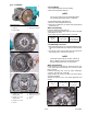
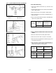
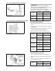
1. Cylinder Head
Surface
(A) Recess
(
B
)
Protrusion
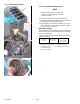
2.3.1.c Valve Recessing
1. Clean the cylinder head surface (1), valve face and
valve seat.
2. Insert the valveinto the head, makingcertain thatthe
valve is fully seated.
3. Measure the valve recessing with a depth gauge.
4. If the measurement exceeds the allowable limit, re-
place the valve.
5. If the measurement still exceeds the allowable limit,
replace the cylinder head.
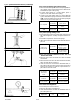
Valve
Recessing
Factory
Specification
0.065 (protrusion) mm to
0.085 (recessing) mm
0.026 (protrusion) in. to
0.033 (recessing) in.
Allowable Limit --
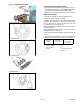
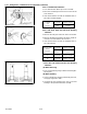
2.3.1.d Clearance Between Valve Stem And Valve
Guide
1. Remove carbon from the valve guide section.
2. Measure the valve stem O.D. with a micrometer .
3. Measurethe valveguidewithasmallholegauge,and
calculate the clearance.
4. If the clearance exceeds the the allowable limit, re-
place the valves. If the clearance stillexceeds the al-
lowable limit, replace the valve guide.
Clearance
Between
Valve Stem
and Guide
Factory
Specification
0.040 to 0.070 mm
0.0016 to 0.0027 in.
Allowable Limit
0.1 mm
0.0039 in.
Valve Stem
O.D.
Factory
Specification
7.960 to 7.975 mm
0.3134 to 0.3139 in.
Valve Guide
I.D.
Factory
Specification
8.015 to 8.030 mm
0.3156 to 0.3161 in.