
Automobile Parts User Manual


2-- 25
62--11362
2.3.2 Timing Gears, Camshaft and Fuel Camshaft (Continued)
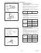
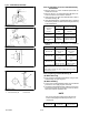
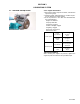
2.3.2.f Camshaft Alignment
1. SupportthecamshaftwithVblocks onasurfaceplate
at both end journals.
2. Setadialindicatorwithitstipontheintermediatejour-
nal.
3. Rotate the camshaft and measure for run--out.
4. If the measurement exceeds the allowable limit, re-
place the camshaft.
Camshaft
Run--out
Allowable
Limit
0.1 mm
0.0004 in.
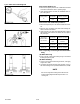
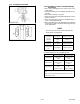
2.3.2.g Cam Height
1. Measure the cam lobe at its largest O.D.with an out-
side micrometer.
2. Ifthemeasurementislessthantheallowablelimit,re-
place the camshaft.
Cam Height
Intake
Factory
Specification
33.27 mm
1.310 in.
Allowable
Limit
33.22 mm
1.308 in.
Cam Height
Exhaust
Factory
Specification
33.47 mm
1.318 in.
Allowable
Limit
33.42 mm
1.316 in.
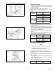
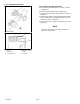
2.3.2.h Camshaft Oil Clearance
1. Measure the camshaft journal O.D. with an outside
micrometer.
2. Measure the cylinder block camshaft bore I.D. with a
cylinder gauge, and calculate the oil clearance.
3. If the oil clearance exceeds the allowable limit, re-
place the camshaft
Camshaft Journal
Clearance
Factory
Specification
0.050 to 0.091 mm
0.0020 to 0.0035 in.
Allowable
Limit
0.15 mm
0.0059 in.
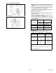
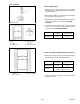
Camshaft Journal
O.D
.
Factory
Specification
39.934 to 39.950 mm
1.5722 to 1.5728 in.
Camshaft Bore
I.D.
Factory
Specification
40.000 to 40.025 mm
1.5748 to 1.5757 in.