WEATHERMAKER® 48/50AJ,AK,AW,AY,A2,A3,A4,A5020-060 Single Package Large Rooftop Units with COMFORTLINK™ Version 5.x Controls Controls, Start-Up, Operation, Service and Troubleshooting CONTENTS Page SAFETY CONSIDERATIONS . . . . . . . . . . . . . . . . . . . . . . . . .2 GENERAL . . . . . . . . . . . . . . . . . . . . . . . . . . . . . . . . . . . . . . . . . . .3 Conventions Used in this Manual. . . . . . . . . . . . . . . . . . . .3 BASIC CONTROL USAGE. . . . . . . . . . . . . . . . . . . . . . . . . .
CONTENTS (cont) SAFETY CONSIDERATIONS Page Indoor Air Quality Control. . . . . . . . . . . . . . . . . . . . . . . . . . 67 • OPERATION • SETTING UP THE SYSTEM • PRE-OCCUPANCY PURGE Dehumidification and Reheat . . . . . . . . . . . . . . . . . . . . . . 69 • SETTING UP THE SYSTEM • OPERATION Temperature Compensated Start. . . . . . . . . . . . . . . . . . . 71 • SETTING UP THE SYSTEM • TEMPERATURE COMPENSATED START LOGIC Carrier Comfort Network® (CCN) System. . . . . . . . . . .
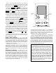
A scheduling function, programmed by the user, controls the unit occupied/unoccupied schedule. Up to 8 different schedules can be programmed. The controls also allow the service person to operate a quick test so that all the controlled components can be checked for proper operation. GENERAL This book contains Start-Up, Controls Operation, Troubleshooting and Service information for the 48/50A Series rooftop units. See Table 1. These units are equipped with ComfortLink™ controls.
marquee, the user can access a built-in test routine that can be used at start-up commissioning to diagnose operational problems with the unit. System diagnostics are enhanced by the use of multiple external sensors for air temperatures, air pressures, refrigerant temperatures, and refrigerant pressures. Unit-mounted actuators provide digital feedback data to the unit control.
Items in the Configuration and Service Test modes are password protected. The display will flash PASS and WORD when required. Use the ENTER and arrow keys to enter the four digits of the password. The default password is 1111. Pressing the ESCAPE and ENTER keys simultaneously will scroll an expanded text description across the display indicating the full meaning of each display point.
Table 2 — Scrolling Marquee Menu Display Structure (ComfortLink™ Display Modes) RUN STATUS Auto View of Run Status (VIEW) SERVICE TEST Service Test Mode (TEST) TEMPERATURES PRESSURES SETPOINTS INPUTS OUTPUTS CONFIGURATION TIME CLOCK Air Temperatures (AIR.T) Air Pressures (AIR.P) Occupied Heat Setpoint (OHSP) General Inputs (GEN.I) Fans (FANS) Unit Configuration (UNIT) Time of Day (TIME) Econ Run Status (ECON) Software Command Disable (STOP) Refrigerant Temperatures (REF.
Controls — Use the following steps for the controls: START-UP IMPORTANT: The unit is shipped with the unit control disabled. To enable the control, set Local Machine Disable (Service TestSTOP) to No. IMPORTANT: Do not attempt to start unit, even momentarily, until all items on the Start-Up Checklist and the following steps have been completed. 1. Set any control configurations that are required (fieldinstalled accessories, etc.).
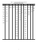
Table 3 — Fan Performance — 48AJ,AK020,025 and 48A2,A3020 Units AIRFLOW (CFM) 4,000 5,000 6,000 7,000 7,500 8,000 9,000 10,000 11,000 12,000 12,500 13,000 AIRFLOW (CFM) 4,000 5,000 6,000 7,000 7,500 8,000 9,000 10,000 11,000 12,000 12,500 13,000 0.2 Rpm Bhp 328 0.62 369 0.97 415 1.43 463 2.01 488 2.36 513 2.74 564 3.61 616 4.64 669 5.84 723 7.20 750 7.95 777 8.75 0.4 Rpm Bhp 406 0.84 439 1.19 477 1.65 519 2.25 541 2.60 564 2.98 612 3.87 661 4.91 711 6.11 762 7.49 788 8.25 814 9.05 0.6 Rpm Bhp 472 1.
Table 5 — Fan Performance — 48AJ,AK,A2,A3035 Units AIRFLOW (Cfm) 7,000 8,000 9,000 10,000 10,500 11,000 12,000 13,000 14,000 15,000 16,000 17,000 17,500 AIRFLOW (Cfm) 7,000 8,000 9,000 10,000 10,500 11,000 12,000 13,000 14,000 15,000 16,000 17,000 17,500 0.2 Rpm 534 590 646 704 733 762 820 879 938 997 1056 1116 1145 Bhp 2.46 3.27 4.23 5.35 5.97 6.63 8.09 9.72 11.54 13.56 15.78 18.20 19.49 0.4 Rpm 584 635 687 742 769 797 853 909 967 1024 1082 1140 1170 2.
Table 7 — Fan Performance — 48AJ,AK,A2,A3040 Units AIRFLOW (Cfm) 8,000 9,000 10,000 11,000 12,000 13,000 14,000 15,000 16,000 17,000 18,000 19,000 20,000 AIRFLOW (Cfm) 8,000 9,000 10,000 11,000 12,000 13,000 14,000 15,000 16,000 17,000 18,000 19,000 20,000 0.2 Rpm 502 552 602 653 704 756 808 861 914 967 1020 1073 1127 Bhp 2.90 3.81 4.89 6.15 7.60 9.24 11.10 13.18 15.49 18.03 20.82 23.87 27.18 0.4 Rpm 550 595 642 689 738 788 838 888 940 991 1043 1095 1147 2.
Table 9 — Fan Performance — 48AJ,AK,A2,A3050 Units AIRFLOW (Cfm) 8,000 9,000 10,000 11,000 12,000 13,000 14,000 15,000 16,000 17,000 18,000 19,000 20,000 AIRFLOW (Cfm) 8,000 9,000 10,000 11,000 12,000 13,000 14,000 15,000 16,000 17,000 18,000 19,000 20,000 0.2 Rpm 512 561 611 662 714 766 819 872 925 979 1032 1086 1140 0.4 Bhp 2.98 3.90 5.00 6.27 7.74 9.41 11.29 13.40 15.74 18.32 21.15 24.24 27.60 Rpm 560 604 651 699 748 798 848 899 951 1003 1055 1108 1161 2.
Table 11 — Fan Performance — 48AJ,AK,A2,A3060 Units AIRFLOW (Cfm) 12,000 14,000 15,000 16,000 17,000 18,000 19,000 20,000 21,000 22,000 23,000 24,000 25,000 26,000 27,000 AIRFLOW (Cfm) 12,000 14,000 15,000 16,000 17,000 18,000 19,000 20,000 21,000 22,000 23,000 24,000 25,000 26,000 27,000 0.2 Rpm Bhp 476 4.33 536 6.19 566 7.28 597 8.48 628 9.80 659 11.25 691 12.82 723 14.53 755 16.37 787 18.35 819 20.48 851 22.75 883 25.17 916 27.76 948 30.49 0.4 Rpm Bhp 534 5.04 588 6.96 617 8.09 645 9.34 674 10.
Table 13 — Fan Performance — 50AJ,AK027,030 and 50A2,A3025-030 Units AIRFLOW (CFM) 4,000 5,000 6,000 7,000 8,000 9,000 10,000 11,000 12,000 13,000 14,000 15,000 AIRFLOW (CFM) 4,000 5,000 6,000 7,000 8,000 9,000 10,000 11,000 12,000 13,000 14,000 15,000 0.2 Rpm Bhp 314 0.54 352 0.85 394 1.26 438 1.79 483 2.44 530 3.23 577 4.15 625 5.22 674 6.45 722 7.85 771 9.41 821 11.15 0.4 Rpm Bhp 394 0.72 422 1.03 456 1.45 495 1.98 536 2.64 579 3.43 624 4.36 669 5.44 715 6.67 762 8.07 810 9.64 857 11.38 0.
Table 15 — Fan Performance — 50AJ,AK036 Units AIRFLOW (Cfm) 0.2 Rpm 431 475 521 568 615 663 712 760 809 859 908 933 7,000 8,000 9,000 10,000 11,000 12,000 13,000 14,000 15,000 16,000 17,000 17,500 AIRFLOW (Cfm) 0.4 Bhp 1.99 2.69 3.53 4.52 5.68 7.01 8.53 10.24 12.15 14.27 16.61 17.87 Rpm 484 523 565 608 652 697 743 790 837 885 933 957 1.2 Rpm 667 692 721 753 788 824 862 902 943 985 1028 1049 7,000 8,000 9,000 10,000 11,000 12,000 13,000 14,000 15,000 16,000 17,000 17,500 AIRFLOW (Cfm) 1.4 Bhp 3.85 4.
Table 17 — Fan Performance — 50AJ,AK041 Units AIRFLOW (Cfm) 0.2 Rpm 475 521 568 615 663 712 760 809 859 908 958 1007 1057 8,000 9,000 10,000 11,000 12,000 13,000 14,000 15,000 16,000 17,000 18,000 19,000 20,000 AIRFLOW (Cfm) 0.4 Bhp 2.69 3.53 4.52 5.68 7.01 8.53 10.24 12.15 14.27 16.61 19.18 21.98 25.02 Rpm 523 565 608 652 697 743 790 837 885 933 981 1030 1079 1.
Table 19 — Fan Performance — 50AJ,AK051 Units AIRFLOW (Cfm) 0.2 Rpm 397 450 477 505 533 561 590 619 648 678 707 737 767 797 827 10,000 12,000 13,000 14,000 15,000 16,000 17,000 18,000 19,000 20,000 21,000 22,000 23,000 24,000 25,000 AIRFLOW (Cfm) 0.4 Bhp 2.69 4.03 4.83 5.74 6.75 7.88 9.12 10.48 11.96 13.57 15.30 17.18 19.20 21.35 23.66 Rpm 461 509 533 558 584 610 637 664 692 719 748 776 804 833 862 Bhp 6.06 7.62 8.55 9.59 10.73 11.98 13.35 14.84 16.45 18.19 20.05 22.06 24.19 26.47 28.
Table 21 — Fan Performance — 48AW,AY020,025 and 48A4,A5020 Units AIRFLOW (CFM) 4,000 5,000 6,000 7,000 7,500 8,000 9,000 10,000 11,000 12,000 12,500 13,000 AIRFLOW (CFM) 4,000 5,000 6,000 7,000 7,500 8,000 9,000 10,000 11,000 12,000 12,500 13,000 0.2 Rpm Bhp 339 0.71 384 1.10 433 1.61 484 2.27 511 2.66 538 3.09 593 4.07 649 5.23 706 6.58 763 8.12 792 8.97 821 9.87 0.4 Rpm Bhp 414 0.97 452 1.37 494 1.89 540 2.56 563 2.95 588 3.38 639 4.37 691 5.54 744 6.89 799 8.45 827 9.30 855 10.20 0.6 Rpm Bhp 478 1.
Table 23 — Fan Performance — 48AW,AY,A4,A5035 Units AIRFLOW (Cfm) 7,000 8,000 9,000 10,000 10,500 11,000 12,000 13,000 14,000 15,000 16,000 17,000 17,500 AIRFLOW (Cfm) 7,000 8,000 9,000 10,000 10,500 11,000 12,000 13,000 14,000 15,000 16,000 17,000 17,500 0.2 Rpm 553 612 672 733 763 794 855 917 980 1042 1105 1168 1200 Bhp 2.59 3.45 4.47 5.67 6.33 7.04 8.60 10.36 12.32 14.49 16.88 19.49 20.88 0.4 Rpm 602 656 712 769 798 828 887 947 1008 1069 1130 1191 1222 2.
Table 25 — Fan Performance — 48AW,AY,A4,A5040 Units AIRFLOW (Cfm) 8,000 9,000 10,000 11,000 12,000 13,000 14,000 15,000 16,000 17,000 18,000 19,000 20,000 AIRFLOW (Cfm) 8,000 9,000 10,000 11,000 12,000 13,000 14,000 15,000 16,000 17,000 18,000 19,000 20,000 0.2 Rpm 526 579 633 687 742 797 852 908 964 1021 1077 1133 1190 Bhp 3.10 4.08 5.24 6.59 8.15 9.92 11.92 14.15 16.63 19.37 22.37 25.65 29.21 0.4 Rpm 573 621 671 723 775 827 881 935 989 1044 1099 1155 — 2.
Table 27 — Fan Performance — 48AW,AY,A4,A5050 Units AIRFLOW (Cfm) 8,000 9,000 10,000 11,000 12,000 13,000 14,000 15,000 16,000 17,000 18,000 19,000 20,000 AIRFLOW (Cfm) 8,000 9,000 10,000 11,000 12,000 13,000 14,000 15,000 16,000 17,000 18,000 19,000 20,000 0.2 Rpm 536 588 642 696 751 807 863 919 975 1032 1089 1146 1203 0.4 Bhp 3.18 4.17 5.35 6.72 8.29 10.09 12.12 14.38 16.90 19.67 22.71 26.04 29.65 Rpm 582 630 680 732 784 837 891 946 1000 1056 1111 1167 1224 2.
Table 29 — Fan Performance — 48AW,AY,A4,A5060 Units AIRFLOW (Cfm) 12,000 14,000 15,000 16,000 17,000 18,000 19,000 20,000 21,000 22,000 23,000 24,000 25,000 26,000 27,000 AIRFLOW (Cfm) 12,000 14,000 15,000 16,000 17,000 18,000 19,000 20,000 21,000 22,000 23,000 24,000 25,000 26,000 27,000 0.2 Rpm Bhp 516 4.81 584 6.90 619 8.13 654 9.49 689 10.99 725 12.64 760 14.43 796 16.37 832 18.47 869 20.74 905 23.17 942 25.78 978 28.56 1015 31.52 1052 34.66 0.4 Rpm Bhp 569 5.54 632 7.69 664 8.96 697 10.36 730 11.
Table 31 — Fan Performance — 50AW,AY027,030 and 50A4,A5025-030 Units AIRFLOW (CFM) 4,000 5,000 6,000 7,000 8,000 9,000 10,000 11,000 12,000 13,000 14,000 15,000 AIRFLOW (CFM) 4,000 5,000 6,000 7,000 8,000 9,000 10,000 11,000 12,000 13,000 14,000 15,000 0.2 Rpm Bhp 325 0.62 366 0.97 411 1.43 459 2.02 508 2.76 560 3.64 612 4.68 665 5.89 718 7.28 772 8.85 826 10.61 881 12.57 0.4 Rpm Bhp 402 0.83 435 1.19 473 1.66 515 2.25 559 2.99 605 3.88 654 4.92 703 6.14 754 7.53 806 9.11 858 10.87 910 12.84 0.
Table 33 — Fan Performance — 50AW,AY036 Units AIRFLOW (Cfm) 0.2 Rpm 451 499 548 599 649 701 753 805 857 910 963 989 7,000 8,000 9,000 10,000 11,000 12,000 13,000 14,000 15,000 16,000 17,000 17,500 AIRFLOW (Cfm) 0.4 Bhp 2.13 2.88 3.78 4.86 6.11 7.54 9.18 11.03 13.09 15.38 17.91 19.26 Rpm 503 546 591 637 685 734 783 833 884 935 986 1012 1.2 Rpm 682 711 744 779 817 857 899 942 987 1032 1078 1102 7,000 8,000 9,000 10,000 11,000 12,000 13,000 14,000 15,000 16,000 17,000 17,500 AIRFLOW (Cfm) 1.4 Bhp 3.
Table 35 — Fan Performance — 50AW,AY041 Units AIRFLOW (Cfm) 0.2 Rpm 499 548 599 649 701 753 805 857 910 963 1016 1069 1122 8,000 9,000 10,000 11,000 12,000 13,000 14,000 15,000 16,000 17,000 18,000 19,000 20,000 AIRFLOW (Cfm) Rpm 546 591 637 685 734 783 833 884 935 986 1038 1090 1142 Bhp 4.87 5.90 7.09 8.47 10.02 11.77 13.73 15.89 18.28 20.91 23.77 26.89 — Rpm 748 778 812 848 886 927 968 1011 1056 1101 1147 1194 — Bhp 7.03 8.13 9.42 10.89 12.55 14.41 16.48 18.75 21.25 23.98 26.
Table 37 — Fan Performance — 50AW,AY051 Units AIRFLOW (Cfm) 0.2 Rpm 429 490 522 554 586 619 652 685 719 753 787 821 855 889 924 10,000 12,000 13,000 14,000 15,000 16,000 17,000 18,000 19,000 20,000 21,000 22,000 23,000 24,000 25,000 AIRFLOW (Cfm) 0.4 Bhp 2.98 4.48 5.39 6.41 7.56 8.83 10.23 11.76 13.44 15.26 17.23 19.35 21.63 24.07 26.67 Rpm 488 543 572 602 632 663 694 725 757 789 822 855 888 921 954 Bhp 6.41 8.14 9.18 10.33 11.60 13.00 14.53 16.20 18.00 19.94 22.03 24.28 26.68 29.24 31.
Table 39 — Motor Limitations Nominal Maximum Bhp 5 BkW 3.73 7.5 5.6 10 7.46 15 11.19 20 14.92 25 18.65 30 22.38 40 29.84 Bhp 5.9 8.7 9.5 10.2 11.8 15.3 18.0 22.4 23.4 28.9 29.4 35.6 34.7 42.0 Nominal Bhp 5 BkW 3.73 7.5 5.6 10 7.46 15 11.19 20 14.92 25 18.65 30 22.38 40 29.84 Bhp 5.9 8.7 9.5 10.2 11.8 15.3 18.0 22.4 23.4 28.9 29.4 35.6 34.7 42.0 HIGH-EFFICIENCY MOTORS Maximum Amps BkW 230 v 460 v 4.40 15.0 7.9 6.49 23.5 — 7.09 — 12.0 7.61 31.0 — 8.80 — 15.0 11.41 46.
Table 40B — Air Quantity Limits (50AJ,AK,AW,AY,A2,A3,A4,A5) UNIT 50AJ,AW,A2,A3020 50AK,AY,A4,A5020 50AJ,AW,A2,A3025 50AK,AY,A4,A5025 50AJ,AW,A2,A4027 50AK,AY,A3,A5027 50AJ,AW,A2,A4030 50AK,AY,A3,A5030 50AJ,AW,A2,A4035 50AJ,AW036 50AK,AY,A3,A5035 50AK,AY036 50AJ,AW,A2,A4040 50AJ,AW041 50AK,AY,A3,A5040 50AK,AY041 50AJ,AW,A2,A4050 50AK,AY,A3,A5050 50AJ,AW051 50AJ,AW,A2,A4060 50AK,AY051 50AK,AY,A3,A5060 COOLING Min CFM 6,000 4,000 7,500 5,000 8,100 5,400 9,000 6,000 10,500 10,500 7,000 7,000 12,000 12,000 8,00
5. See the Exhaust Options section on page 29 for additional exhaust option configurations. Variable Air Volume Units Using Return Air Sensor or Space Temperature Sensor — To con- figure the unit, perform the following: 1. The type of control is configured under Configuration UNITC.TYP. Set C.TYP to 1 (VAV-RAT) for return air sensor. Set C.TYP to 2 (VAV-SPT) for space temperature sensor. NOTE: For VAV with a space sensor (VAV-SPT), under ConfigurationUNITSENSSPT.
correct value for hours, in 24-hour (military) time. Press ENTER and hour value is saved and the minutes digits will start flashing. Use the same procedure to display and save the desired minutes value. Press ESCAPE. 4. Configure the unoccupied time for period 1 (UNC). Scroll down to UNC and press ENTER to go into Edit mode. The first two digits of the 00.00 will start flashing. Use the UP or DOWN key to display the correct value for hours, in 24-hour (military) time.
individually. After starting each compressor, the control will check the suction pressure after 5 seconds of run time. If the control does not see a sufficient decrease in suction pressure after 5 seconds, mechanical cooling will be shut down, and an alarm will be generated (A140). This alarm requires a manual reset. If this alarm occurs, do not attempt a restart of the compressor and do not attempt to start any other compressors until the wiring to the unit has been corrected.
A 4 to 20 mA input that can reduce or limit capacity linearly to a set point percentage. In either case, it will be necessary to install a controls expansion module (CEM). DEMAND LIMIT DISCRETE INPUTS — First, set DM.L.S in ConfigurationDMD.L to 1 (2 switches). When InputsGEN.IDL.S1 (Demand Switch no. 1) is OFF, the control will not set any limit to the capacity, and when ON, the control sets a capacity limit to the ConfigurationDMD.LD.L.S1 set point. Likewise, when InputsGEN.IDL.
The 4 to 20 mA signal from the sensor wired to TB5-6 and 7 is scaled to an equivalent indoor CO2 (IAQ) by the parameters IQ.R.L and IQ.R.H located under the Configuration IAQAQ.S.R menu. The parameters are defined such that 4 mA = IQ.R.L and 20 mA = IQ.R.H. When the differential air quality DAQ (IAQ – OAQ.U) exceeds the DAQ.H set point (ConfigurationIAQAQ.SP menu) and the supply fan is on, the economizer minimum vent position (Configuration IAQDCV.CEC.
(“Internal Failure”) System Mode Test — When the system mode is Test, the control is limited to the Test mode and is controllable via the local displays (scrolling marquee and Navigator™ display) or through the factory service test control. The System Test modes are Factory Test Enabled and Service Test Enabled. See the Service Test Mode section for details on test control in this mode. 1. Factory Test mode (“Factory test enabled”) 2.
System Mode = OFF? No FireSmoke Control System Mode Yes Inputs -> FIRE -> FSD in alarm? No Unit not in factory test AND fire-smoke control mode is alarming? No Yes HVAC Mode = OFF (Disabled) Inputs -> FIRE -> PRES in alarm? Yes No Inputs -> FIRE -> EVAC in alarm? Yes HVAC Mode = OFF (Fire Shutdown) No Yes HVAC Mode = OFF (Pressurization) HVAC Mode = OFF (Evacuation) HVAC Mode = OFF (Purge) Exceptions Config->UNIT-> C.
accurate return-air temperature before the return-air temperature is allowed to call out any mode. • C.TYP = 3 (TSTAT-MULTI) This configuration will force the control to monitor the thermostat inputs to make a determination of mode. Unlike traditional 2-stage thermostat control, the unit is allowed to use multiple stages of cooling control and perform VAVtype operation. The control will be able to call out a LOW COOL or a HIGH COOL mode and maintain a low or high cool supply air set point. • C.
Suction Pressure Transducer Type (SP.XR) — This configuration specifies the type of suction pressure transducer that is being used. Set SP.XR to 0 for support of a pressure transducer with a range of 0 to 135 psig. Set SP.XR to 1 for support of a pressure transducer with a range of 0 to 200 psig. NOTE: The 48/50A2,A3,A4,A5 units do not require a change to the SP.XR factory default setting. Refrigerant Type (RFG.T) — This configuration specifies the type of refrigerant used in the unit. Configuration RFG.
mechanical cooling to allow for the greatest use of free cooling. When both mechanical cooling and the economizer are being used, the control will use the economizer to provide better temperature control and limit the cycling of the compressors. The control also checks on various other operation parameters in the unit to make sure that safeties are not exceeded and the compressors are reliably operated. The A Series ComfortLink™ control system offers two basic control approaches to mechanical cooling.
SUPPLY AIR RESET CONFIGURATION — Supply Air Reset can be used to modify the current cooling supply air set point. Supply Air Reset is applicable to control types, C.TYP = 1,2,3, and 5. The configurations for reset can be found at the local display under ConfigurationEDT.R. See Table 46. EDT Reset Configuration (RS.CF) — This configuration applies to several machine control types (Configuration UNITC.TYP = 1,2,3, and 5).
Table 47 — Cooling Configuration ITEM COOL Z.GN MC.LO C.FOD MLV M.M. HPSP A1.EN A2.EN B1.EN B2.EN CS.A1 CS.A2 CS.B1 CS.B2 REV.R H.SST EXPANSION COOLING CONFIGURATION Capacity Threshold Adjst Compressor Lockout Temp Fan-Off Delay, Mech Cool Min. Load Valve (HGBP)? Motor Master Control ? Head Pressure Setpoint Enable Compressor A1 Enable Compressor A2 Enable Compressor B1 Enable Compressor B2 CSB A1 Feedback Alarm CSB A2 Feedback Alarm CSB B1 Feedback Alarm CSB B2 Feedback Alarm Rev.
will run until the motor protector trips, which occurs up to 90 minutes later. Advanced scroll temperature protection will reset automatically before the motor protector resets, which may take up to 2 hours. COMPRESSOR TIME GUARDS — The control will not allow any output relay to come on within 3 seconds of any other output relay.
The advantage of this offset technique is that the control can safely enforce a vent mode without worrying about crossing set points. Even more importantly, under CCN linkage, the occupied heating set point may drift up and down and this method ensures a guaranteed separation in degrees Fahrenheit between the calling out of a heating or cooling mode at all times.
Table 48 — Cool/Heat Set Point Offsets Configuration ITEM D.LV.T L.H.ON H.H.ON L.H.OF L.C.ON H.C.ON L.C.OF C.T.LV H.T.LV C.T.TM H.T.TM EXPANSION COOL/HEAT SETPT. OFFSETS Dmd Level Lo Heat On Dmd Level(+) Hi Heat On Dmd Level(-) Lo Heat Off Dmd Level Lo Cool On Dmd Level(+) Hi Cool On Dmd Level(-) Lo Cool Off Cool Trend Demand Level Heat Trend Demand Level Cool Trend Time Heat Trend Time RANGE -1 - 2 0.5 - 20.0 0.5 - 2 -1 - 2 0.5 - 20.0 0.5 - 2 0.1 - 5 0.
If the set point cannot be satisfied or the economizer is not active, then cooling will be brought on one stage at a time when the evaporator discharge temperature (EDT) is greater the 1.5° F above the current cooling control point. A start-up time delay of 10 minutes and steady state delay after a compressor is energized of 5 minutes is enforced. If both circuits of mechanical cooling are running, then the economizer will attempt to control to 48 F.
Table 52 — Staging Sequence with Hot Gas Bypass — 48/50AK,AY020-027 and Multi-Stage 48/50AJ,AW020-027 STAGE COMP A1 A2 B1 UNIT 020 025 027 0 1 OFF OFF OFF ON* OFF OFF 0% 0% 0% 18% 17% 21% SEQUENCE 1 2 3 Compressor Status ON ON OFF ON OFF OFF Unit Capacity 48/50A 33% 67% 30% 65% 33% 67% 4 5 0 1 OFF ON ON ON ON ON OFF OFF OFF OFF ON* OFF 67% 70% 67% 100% 100% 100% 0% 0% 0% 18% 22% 21% SEQUENCE 2 2 3 Compressor Status OFF ON ON ON OFF OFF Unit Capacity 48/50A 33% 67% 35% 65% 33% 67% 4 5
Table 57 — Staging Sequence without Hot Gas Bypass — 48/50A3,A5020-027 and Multi-Stage 48/50A2,A4020-027 STAGE SEQUENCE 1 1 2 Compressor Status ON ON OFF OFF OFF ON Unit Capacity 48/50A 30% 70% 33% 67% 33% 67% 0 COMP A1 A2 B1 UNIT 020 025 027 OFF OFF OFF 0% 0% 0% 3 0 ON ON ON OFF OFF OFF 100% 100% 100% 0% 0% 0% SEQUENCE 2 1 2 Compressor Status OFF OFF ON ON OFF ON Unit Capacity 48/50A 30% 70% 33% 67% 33% 67% 3 ON ON ON 100% 100% 100% Table 58 — Staging Sequence with Hot Gas Bypass — 48/50A3,A50
COOLING MODE DIAGNOSTIC HELP — To quickly determine the current trip points for the cooling modes, the Run Status sub-menu at the local display allows the user to view the calculated start and stop points for both the cooling and heating trip points. The following sub-menu can be found at the local display under Run StatusTRIP. See Table 61. The controlling temperature is “TEMP” and is in the middle of the table for easy reference. The HVAC mode can also be viewed at the bottom of the table.
Table 62 — Run Status Cool Display ITEM COOL C.CAP CUR.S REQ.S MAX.S DEM.L SUMZ SMZ ADD.R SUB.R R.PCT Y.MIN Y.PLU Z.MIN Z.PLU H.TMP L.TMP PULL SLOW EXPANSION COOLING INFORMATION Current Running Capacity Current Cool Stage Requested Cool Stage Maximum Cool Stages Active Demand Limit COOL CAP.
MAT Calc Config (MAT.S) — This configuration gives the user two options in the processing of the mixed-air temperature (MAT) calculation: • MAT.S = 0 There will be no MAT calculation. • MAT.S = 1 The control will attempt to learn MAT over time. Any time the system is in a vent mode and the economizer stays at a particular position for long enough, MAT = EDT. Using this method, the control has an internal table whereby it can more closely determine the true MAT value. • MAT.
Table 63 — Demand Limit Configuration ITEM DMD.L DM.L.S D.L.20 SH.NM SH.DL SH.TM D.L.S1 D.L.S2 EXPANSION DEMAND LIMIT CONFIG. Demand Limit Select Demand Limit at 20 ma Loadshed Group Number Loadshed Demand Delta Maximum Loadshed Time Demand Limit Sw.1 Setpt. Demand Limit Sw.2 Setpt.
Table 64 — Condenser Fan Staging FAN RELAY OFC1,4* (MBB - RELAY 6) OFC2 (MBB - RELAY 5) OFC3 C.A1-AUX or C.A2-AUX OFC1* C.B1-AUX or C.B2-AUX 020-035 OFM1 OFM2 NA NA 036-050 OFM1, OFM2 OFM3, OFM4 NA NA 48/50A UNIT SIZE 051,060 OFM1, OFM2 OFM3, OFM4, OFM5, OFM6 NA NA 060 with MCHX OFM4 OFM2 OFM3 OFM1 * For size 60 ton units with MCHX condensers, MBB – Relay 6 drives OFC4 and compressor contactor B1 or B2 auxiliary contacts drive OFC1.
Table 65 — Heating Configuration ITEM HEAT HT.CF HT.SP OC.EN LAT.M G.FOD E.FOD SG.CF HT.ST CAP.M M.R.DB S.G.DB RISE LAT.L LIM.M SW.H.T SW.L.T HT.P HT.D HT.TM EXPANSION HEATING CONFIGURATION Heating Control Type Heating Supply Air Setpt Occupied Heating Enabled MBB Sensor Heat Relocate Fan Off Delay, Gas Heat Fan Off Delay, Elec Heat STAGED GAS CONFIGS Staged Gas Heat Type Max Cap Change per Cycle S.Gas DB min.dF/PID Rate St.Gas Temp.
To get out of a HIGH HEAT mode, the controlling temperature must rise above the heating set point minus L.H.ON plus L.H.OF/2. The Run Status table in the local display allows the user to see the exact trip points for both the heating and cooling modes without doing the calculations. Heat Trend Demand Level (H.T.LV) — This is the change in demand that must be seen within the time period specified by H.T.TM in order to hold off a HIGH HEAT mode regardless of demand.
Heat Control Prop. Gain (HT.P) — This configuration is the proportional term for the PID which runs in the HVAC mode LOW HEAT. Heat Control Derv. Gain (HT.D) — This configuration is the derivative term for the PID which runs in the HVAC mode LOW HEAT. Heat PID Rate Config (HT.TM) — This configuration is the PID run time rate.
Table 68 — Staged Gas Configuration ITEM EXPANSION SG.CF STAGED GAS CONFIGS HT.ST Staged Gas Heat Type CAP.M Max Cap Change per Cycle M.R.DB S.Gas DB min.dF/PID Rate S.G.DB St.Gas Temp. Dead Band RISE Heat Rise dF/sec Clamp LAT.L LAT Limit Config LIM.M Limit Switch Monitoring? SW.H.T Limit Switch High Temp SW.L.T Limit Switch Low Temp HT.P Heat Control Prop. Gain HT.D Heat Control Derv. Gain HT.TM Heat PID Rate Config *Some configurations are model number dependent. RANGE 0-4 5 - 45 0-5 0-5 0.05 - 0.
Table 69B — Staged Gas Heat — 48A2,A3,A4,A5 Units UNIT SIZE HEAT CAPACITY Low High Low High Low High 020-030 035-050 060 UNIT MODEL NO. POSITION NO. 5 S T S T S T ConfigurationHEATSG.CF HT.ST ENTRY VALUE 1 = 5 STAGE 2 = 7 STAGE 1 = 5 STAGE 1 = 5 STAGE 4 = 11 STAGE 3 = 9 STAGE Table 70 — Staged Gas Heat Control Steps (ConfigurationHEATSG.CFHT.
Table 73 — Staged Gas Heat Control Steps (ConfigurationHEAT SG.CTHT.
pressure and calculates the error from set point. This error is simply the duct static pressure set point minus the measured duct static pressure. The error becomes the basis for the proportional term of the PID. The routine also calculates the integral of the error over time, and the derivative (rate of change) of the error. A value is calculated as a result of this PID routine, and this value is then used to create an output signal used to adjust the VFD to maintain the static pressure set point.
directly to the 0 to 3 in. wg of reset. Therefore 2 mA reset is 2/16 * 3 in. wg = 0.375 in. wg of reset. If the static pressure set point (SP.SP) = 1.5 in. wg, then the static pressure control point for the system will be reset to 1.5 – 0.375 = 1.125 in. wg. When SP.RS = 4, the static pressure reset function acts to provide direct VFD speed control where 4 mA = 0% speed and 20 mA = 100% (SP.MN and SP.MX will override). Note that SP.CF must be set to 1 (VFD Control), prior to configuring SP.RS = 4.
case, the installer could enter 3.0 in. wg as the supply static pressure set point and allow the air terminal system to dynamically adjust the supply duct static pressure set point as required. The system will determine the actual set point required delivering the required airflow at every terminal under the current load conditions. The set point will always be the lowest value under the given conditions.
Table 76 — Static Pressure Reset Related Points ITEM Inputs 4-20 SP.M 4-20 SP.M.T 4-20 SP.R.M RSET SP.RS Outputs Fans S.VFD EXPANSION RANGE 4-20 -2.0 - +2.0 4-20 0.0-3.0 mA mA mA in.
modulate to the same control point (Sum Z) that is used to control capacity staging. The advantage is lower compressor cycling coupled with tighter temperature control. Setting this option to No will cause the economizer, if it is able to provide free cooling, to open to the Economizer Max. Position (EC.MX) during mechanical cooling. ECONOMIZER OPERATION — There are four potential elements which are considered concurrently which determine whether the economizer is able to provide free cooling: 1.
Table 79 — Economizer Configuration Table ITEM EC.EN EC.MN EC.MX E.TRM E.SEL OA.E.C OA.EN OAT.L O.DEW ORH.S E.TYP EC.SW E.CFG E.P.GN E.RNG E.SPD E.DBD UEFC FC.CF FC.TM FC.L.O EXPANSION Economizer Installed? Economizer Min.Position Economizer Max.Position Economzr Trim For SumZ ? Econ ChangeOver Select OA Enthalpy ChgOvr Selct Outdr.Enth Compare Value High OAT Lockout Temp OA Dewpoint Temp Limit Outside Air RH Sensor Economizer Control Type Economizer Switch Config ECON.OPERATION CONFIGS Economizer Prop.
cooling” is located at Run StatusVIEWEC.C.P. This is the economizer control point. The control selects set points differently, based on the control type of the unit. This control type can be found at ConfigurationUNITC.TYP. There are 6 types of control. C.TYP = 1 VAV-RAT C.TYP = 2 VAV-SPT C.TYP = 3 TSTAT Multi-Staging C.TYP = 4 TSTAT 2 Stage C.TYP = 5 SPT Multi-Staging C.TYP = 6 SPT 2 Stage If the economizer is not allowed to do free cooling, then EC.C.P = 0.
Table 80 — Economizer Run Status Table ITEM ECN.P ECN.C ACTV DISA UNAV R.EC.D DBC DEW DDBC OAEC DEC EDT OAT FORC SFON CLOF OAQL HELD DH.DS O.AIR OAT OA.RH OA.E OA.D.T EXPANSION Economizer Act.Curr.Pos. Economizer Act.Cmd.Pos. Economizer Active ? ECON DISABLING CONDITIONS Econ Act. Unavailable? Remote Econ. Disabled? DBC - OAT Lockout? DEW - OA Dewpt.Lockout? DDBD- OAT > RAT Lockout? OAEC- OA Enth Lockout? DEC - Diff.Enth.
The number of power exhaust stages available for this control algorithm is a function of the number of motors it supports. This number of motors is defined by the ConfigurationBP BP.MT configuration. Table 83 illustrates the staging tables for this control algorithm based on BP.MT. The following configurations are used in the controlling of building pressure with this algorithm: • ConfigurationBPB.CFGBP.HP (building pressure high threshold level) • ConfigurationBPB.CFGBP.
Table 83 — Power Exhaust Staging (BP.CF = 2) BP.MT = 1 (4 motors) Power Exhaust Stage 0 Power Exhaust Stage 1 Power Exhaust Stage 2 Power Exhaust Stage 3 Power Exhaust Stage 4 PE.A OFF ON OFF ON ON PE.B OFF OFF ON ON ON PE.C OFF OFF OFF OFF ON BP.MT = 2 (6 motors) Power Exhaust Stage 0 Power Exhaust Stage 1 Power Exhaust Stage 2 Power Exhaust Stage 3 Power Exhaust Stage 4 Power Exhaust Stage 5 Power Exhaust Stage 6 PE.A OFF ON OFF ON ON OFF ON PE.B OFF OFF ON ON OFF ON ON PE.
configurable amount, which is referred to as Differential Air Quality Low Limit (DAQ.L). If OAQ is not being measured, OAQ can be manually configured. It should be set at around 400 to 450 ppm or measured with a handheld sensor during the commissioning of the unit. The OAQ reference level can be set using the OAQ Reference Set Point (OAQ.U). When the differential between IAQ and OAQ reaches the configurable Diff. Air Quality Hi Limit (DAQ.H), then the economizer position will be EC.MN.
• IQ.A.C = 4 (10K potentiometer minimum position) — With a 10K linear potentiometer connected to TB5-6 and 7, the economizer minimum position will be scaled linearly from 0% (0 kilo-ohms) to EC.MX (10 kilo-ohms). IAQ Analog Fan Config (ConfigurationIAQAQ.CF IQ.A.F) — This configuration is used to configure the control of the indoor fan. If this option is used then the IAQ sensor must be in the space and not in the return duct. It has the following configurations: • IQ.A.
IAQ Econo Override Pos (ConfigurationIAQAQ.SP IQ.O.P) — This configuration is the position that the economizer goes to when override is in effect. Diff. Air Quality Lo Limit (ConfigurationIAQAQ.SP DAQ.L) — This is the differential CO2 level at which IAQ control of the dampers will be initiated. Diff. Air Quality Hi Limit (ConfigurationIAQ AQ.SP DAQ.H) — This is the differential CO2 level at which IAQ control of the dampers will be at maximum and the dampers will be at the Configuration IAQDCV.
Table 84 — Indoor Air Quality Configuration ITEM DCV.C EC.MN IAQ.M AQ.CF IQ.A.C IQ.A.F IQ.I.C IQ.I.F OQ.A.C AQ.SP IQ.O.P DAQ.L DAQ.H D.F.OF D.F.ON IAQ.R OAQ.L OAQ.U AQ.S.R IQ.R.L IQ.R.H OQ.R.L OQ.R.H IAQ.P IQ.PG IQ.P.T IQ.P.L IQ.P.H IQ.L.O EXPANSION DCV ECONOMIZER SETPOINTS Economizer Min.Position IAQ Demand Vent Min.Pos. AIR QUALITY CONFIGS IAQ Analog Sensor Config IAQ 4-20 ma Fan Config IAQ Discrete Input Config IAQ Disc.In.
maintain diagnostics, although the end user will see a Dehumidification mode at the display. In addition, for multi-stage cooling units the cooling control point will be set to ConfigurationDEHUD.C.SP (no SASP reset is applied). • Reheat When Cooling Demand is Present — For reheat control during dehumidification: If reheat follows an offset subtracted from return-air temperature (ConfigurationDEHUD.SEL = 2), then no heating will be initiated and the alarm relay will be energized.
Table 86 — CCN Configuration ITEM CCN CCNA CCNB BAUD BROD TM.DT OAT.B ORH.B OAQ.B G.S.B B.ACK SC.OV SCH.N HOL.T O.T.L. OV.EX SPT.O T58.O GL.
Air Temperature Leaving Supply Fan Sensor (SAT.T) — This variable is used to adjust the supply fan temperature sensor reading. The sensor reading can be adjusted ± 10° F to match the actual measured temperature. Return Air Temperature Sensor Trim (RAT.T) — This variable is used to adjust the return air temperature sensor reading. The sensor reading can be adjusted ± 10° F to match the actual measured temperature. Outdoor Air Temperature Sensor Trim (OAT.
Discharge Pressure Circuit A Trim (DP.A.T) — This variable is used to adjust the discharge pressure sensor reading for circuit A. The sensor reading can be adjusted ± 50 psig to match the actual measured pressure. Used on 48/ 50A2,A3,A4,A5 units only. Discharge Pressure Circuit B Trim (DP.B.T) — This variable is used to adjust the discharge pressure sensor reading for circuit B. The sensor reading can be adjusted ± 50 psig to match the actual measured pressure. Used on 48/ 50A2,A3,A4,A5 units only.
Table 89 — Switch Logic Configuration ITEM SW.LG FTS.L IGC.L RMI.L ECS.L SFS.L DL1.L DL2.L IAQ.L FSD.L PRS.L EVC.L PRG.L EXPANSION SWITCH LOGIC: NO / NC Filter Status Inpt-Clean IGC Feedback - Off RemSw Off-Unoc-Strt-NoOv Economizer Switch - No Fan Status Sw. - Off Dmd.Lmt.Sw.1 - Off Dmd.Lmt.2 Dehumid - Off IAQ Disc.Input - Low Fire Shutdown - Off Pressurization Sw. - Off Evacuation Sw. - Off Smoke Purge Sw.
Table 92 — Remote Switch Logic Configuration REMOTE SWITCH LOGIC CONFIGURATION (RMI.L) OPEN CLOSED SWITCH STATUS REMOTE INPUT STATE (REMT) OPEN CLOSED OPEN CLOSED OFF ON ON OFF 0 REMOTE SWITCH CONFIGURATION (RM.CF) 1 2 3 No Remote Switch Occ-Unocc Switch Start/Stop Override xxxxx xxxxx xxxxx xxxxx Unoccupied Occupied Occupied Unoccupied Start Stop Stop Start No Override Override Override No Override Monday In Period (PER.
Table 93 — Time Clock Configuration ITEM TIME HH.MM DATE MNTH DOM DAY YEAR SCH.L PER.1 PER.1DAYS PER.1DAYSMON PER.1DAYSTUE PER.1DAYSWED PER.1DAYSTHU PER.1DAYSFRI PER.1DAYSSAT PER.1DAYSSUN PER.1DAYSHOL PER.1OCC PER.1UNC Repeat for periods 2-8 HOL.L HD.01 HD.01MON HD.01DAY HD.01LEN Repeat for holidays 2-30 DAY.S DS.ST DS.STST.MN DS.STST.WK DS.STST.DY DS.STMIN.A DS.SP DS.SPSP.MN DS.SPSP.WK DS.SPSP.DY DS.SPMIN.
the suction and discharge pressure of circuits A and B. The pressure/voltage characteristics of these transducers are shown in Tables 103 and 104. The accuracy of these transducers can be verified by connecting an accurate pressure gage to the second refrigerant port in the suction line. Transducer Troubleshooting — On 48/50AJ,AK, AW,AY units, the electronic control uses 2 suction pressure transducers to measure the suction pressure of circuits A and B.
Table 94 — Cooling Service Analysis (cont) PROBLEM COMPRESSOR RUNNING BUT COOLING INSUFFICIENT Suction Pressure Low 1. Refrigerant charge low. 2. Head pressure low. 3. Air filters dirty. 4. Expansion valve power head defective. 5. Indoor coil partially iced. 6. Indoor airflow restricted. Suction Pressure High Heat load excessive. UNIT OPERATES TOO LONG OR CONTINUOUSLY 1. Low refrigerant charge. 2. Control contacts fused. 3. Air in system. 4. Partially plugged expansion valve or filter drier.
Table 95 — Gas Heating Service Analysis PROBLEM Burners Will Not Ignite. CAUSE Active alarm. No power to unit. No power to IGC (Integrated Gas Control). Heaters off due to time guard to prevent short cycling. Control calling for Cooling. No gas at main burners. Inadequate Heating. Water in gas line. Dirty air filters. Gas input too low. Control calling for W1only (low heat). Unit undersized for load. Restricted airflow. Too much outdoor air. Limit switch cycles main burners. Poor Flame Characteristics.
IDM — IGC — LEGEND Induced-Draft Motor Integrated Gas Unit Controller NOTE: Thermostat Fan Switch in the “AUTO” position. A48-5656 Fig.
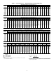
Table 97 — 5K Thermistor Temperature vs. Resistance (SCT Sensors) (English) TEMP (F) –25 –24 –23 –22 –21 –20 –19 –18 –17 –16 –15 –14 –13 –12 –11 –10 –9 –8 –7 –6 –5 –4 –3 –2 –1 0 1 2 3 4 5 6 7 8 9 10 11 12 13 14 15 16 17 18 19 20 21 22 23 24 25 26 27 28 29 30 31 32 33 34 35 36 37 38 39 40 41 42 43 44 45 46 47 48 49 50 51 52 53 54 55 56 57 58 VOLTAGE DROP (V) 3.699 3.689 3.679 3.668 3.658 3.647 3.636 3.624 3.613 3.601 3.588 3.576 3.563 3.550 3.536 3.523 3.509 3.494 3.480 3.465 3.450 3.434 3.418 3.402 3.
Table 98 — 5K Thermistor Temperature vs. Resistance (SCT Sensors) (SI) TEMP (C) –32 –31 –30 –29 –28 –27 –26 –25 –24 –23 –22 –21 –20 –19 –18 –17 –16 –15 –14 –13 –12 –11 –10 –9 –8 –7 –6 –5 –4 –3 –2 –1 0 1 2 3 4 5 6 7 8 9 10 11 12 13 14 VOLTAGE DROP (V) 3.705 3.687 3.668 3.649 3.629 3.608 3.586 3.563 3.539 3.514 3.489 3.462 3.434 3.406 3.376 3.345 3.313 3.281 3.247 3.212 3.177 3.140 3.103 3.065 3.025 2.985 2.945 2.903 2.860 2.817 2.774 2.730 2.685 2.639 2.593 2.547 2.500 2.454 2.407 2.360 2.312 2.265 2.217 2.
Table 99 — 10K Thermistor vs. Resistance (T55, T56, OAT, RAT, EDT, LAT Sensors) (English) TEMP (F) –25 –24 –23 –22 –21 –20 –19 –18 –17 –16 –15 –14 –13 –12 –11 –10 –9 –8 –7 –6 –5 –4 –3 –2 –1 0 1 2 3 4 5 6 7 8 9 10 11 12 13 14 15 16 17 18 19 20 21 22 23 24 25 26 27 28 29 30 31 32 33 34 35 36 37 38 39 40 41 42 43 44 45 46 47 48 49 50 51 52 53 54 55 56 57 58 59 60 VOLTAGE DROP (V) 4.758 4.750 4.741 4.733 4.724 4.715 4.705 4.696 4.686 4.676 4.665 4.655 4.644 4.633 4.621 4.609 4.597 4.585 4.572 4.560 4.546 4.
Table 100 — 10K Thermistor vs. Resistance (T55, T56, OAT, RAT, EDT, LAT Sensors) (SI) TEMP (C) –32 –31 –30 –29 –28 –27 –26 –25 –24 –23 –22 –21 –20 –19 –18 –17 –16 –15 –14 –13 –12 –11 –10 –9 –8 –7 –6 –5 –4 –3 –2 –1 0 1 2 3 4 5 6 7 8 9 10 11 12 13 14 VOLTAGE DROP (V) 4.762 4.748 4.733 4.716 4.700 4.682 4.663 4.644 4.624 4.602 4.580 4.557 4.533 4.508 4.482 4.455 4.426 4.397 4.367 4.335 4.303 4.269 4.235 4.199 4.162 4.124 4.085 4.044 4.003 3.961 3.917 3.873 3.828 3.781 3.734 3.686 3.637 3.587 3,537 3.485 3.
Table 102 — Suction Pressure Transducer Pressure (PSIG) vs. Voltage (SP-A, SP-B, SP.XR = 1, 48/50AJ,AK,AW,AY Units Only) PRESSURE (PSIG) 0 1 2 3 4 5 6 7 8 9 10 11 12 13 14 15 16 17 18 19 20 21 22 23 24 25 26 27 28 29 30 31 32 33 34 35 36 37 38 39 40 41 42 43 44 45 46 47 48 49 50 VOLTAGE DROP (V) 0.500 0.520 0.540 0.560 0.580 0.600 0.620 0.640 0.660 0.680 0.700 0.720 0.740 0.760 0.780 0.800 0.820 0.840 0.860 0.880 0.900 0.920 0.940 0.960 0.980 1.000 1.020 1.040 1.060 1.080 1.100 1.120 1.140 1.160 1.180 1.
Table 103 — Suction Pressure Transducer (PSIG) vs. Voltage (SP-A, SP-B, 48/50A2,A3,A4,A5 Units Only) PRESSURE (PSIG) 0 1 2 3 4 5 6 7 8 9 10 11 12 13 14 15 16 17 18 19 20 21 22 23 24 25 26 27 28 29 30 31 32 33 34 35 36 37 38 39 40 41 42 43 44 45 46 47 48 49 50 51 52 53 54 55 56 57 58 59 60 61 62 63 64 65 66 67 68 69 70 71 72 73 74 75 76 77 78 79 80 81 82 83 84 85 86 87 88 89 90 91 92 93 94 95 96 97 98 99 100 101 102 103 104 105 VOLTAGE DROP (V) 0.466 0.476 0.486 0.495 0.505 0.515 0.525 0.535 0.545 0.554 0.
Table 104 — Discharge Pressure Transducer (PSIG) vs. Voltage (DP-A, DP-B, 48/50A2,A3,A4,A5 Units Only) PRESSURE (PSIG) 14.5 16 17 18 19 20 21 22 23 24 25 26 27 28 29 30 31 32 33 34 35 35 36 37 38 39 40 41 42 43 44 45 46 47 48 49 50 51 52 53 54 55 56 57 58 59 60 61 62 63 64 65 66 67 68 69 70 71 72 73 74 75 76 77 78 79 80 81 82 83 84 85 86 87 88 89 90 91 92 93 94 VOLTAGE DROP (V) 0.500 0.509 0.515 0.521 0.528 0.534 0.540 0.546 0.552 0.558 0.564 0.570 0.577 0.583 0.589 0.595 0.601 0.607 0.613 0.620 0.626 0.
Table 104 — Discharge Pressure Transducer (PSIG) vs. Voltage (DP-A, DP-B, 48/50A2,A3,A4,A5 Units Only) (cont) PRESSURE (PSIG) 338 339 340 341 342 343 344 345 346 347 348 349 350 351 352 353 354 355 356 357 358 359 360 361 362 363 364 365 366 367 368 369 370 371 372 373 374 375 376 377 378 379 380 381 382 383 384 385 386 387 388 389 390 391 392 393 394 395 396 397 398 399 400 401 402 403 404 405 406 407 408 409 410 411 412 413 414 415 416 417 418 419 420 VOLTAGE DROP (V) 2.483 2.489 2.495 2.502 2.508 2.
Run StatusVIEWHT.ST — This variable displays the current number of heating stages active (for staged gas control option only). Compare to following point. Run StatusVIEWH.MAX — This variable displays the maximum number of heat stages available for this model. ECONOMIZER RUN STATUS — The Economizer Run Status display table provides information about the economizer and can be used to troubleshoot economizer problems. See Table 106.
Slow Change Cap Override (SLOW) — With a rooftop unit, the design rise at 100% total unit capacity is generally around 30 F. For a unit with 4 stages, each stage represents about 7.5F of change to EDT. If stages could reliably be cycled at very fast rates, the set point could be maintained very precisely. Since it is not desirable to cycle compressors more than 6 cycles per hour, slow change override takes care of keeping the PID under control when “relatively” close to set point.
Table 107 — Cooling Information Display Table ITEM COOL C.CAP CUR.S REQ.S MAX.S DEM.L SUMZ SMZ ADD.R SUB.R R.PCT Y.MIN Y.PLU Z.MIN Z.PLU H.TMP L.TMP PULL SLOW EXPANSION COOLING INFORMATION Current Running Capacity Current Cool Stage Requested Cool Stage Maximum Cool Stages Active Demand Limit COOL CAP.
Table 112 — Time Guard Display Table ITEM TMGD TG.A1 TG.A2 TG.B1 TG.B2 TG.H1 TG.H2 TG.H3 TG.H4 TG.H5 TG.
Table 114 — Alert and Alarm Codes ALARM OR ALERT DESCRIPTION NUMBER A051 Circuit A, Compressor 1 Stuck On Failure ACTION TAKEN BY CONTROL Turn off all compressors Compressor locked off Welded contact High pressure switch, compressor current, wiring error Exceeded 3 strike limit Welded contact High pressure switch, compressor current, wiring error Exceeded 3 strike limit Welded contact High pressure switch, compressor current, wiring error Exceeded 3 strike limit Welded contact High pressure switch, compr
Table 114 — Alert and Alarm Codes (cont) ALARM OR ALERT NUMBER DESCRIPTION T300 Space Temperature Below Limit T301 Space Temperature Above Limit T302 Supply Temperature Below Limit T303 ACTION TAKEN BY CONTROL Stop cooling, but continue to heat Stop heating, but continue to cool RESET METHOD PROBABLE CAUSE Automatic Outdoor dampers stuck, no load Automatic High load, dampers open Continue to run unit Automatic Supply Temperature Above Limit Continue to run unit Automatic T304 Return Te
The cause of the alert is usually a faulty thermistor, a shorted or open thermistor caused by a wiring error, or a loose connection. T072 (Evaporator Discharge Reset Sensor Failure) — If the unit is configured to use the remote EDT 4 to 20 mA reset input (ConfigurationEDT.RRES.S) and the sensor reading is less than 2 mA then the alert will occur. When this occurs the control will default to the internal set points. The sensor is connected to the optional CEM module.
any elements of the control which requires its use including economizer differential enthalpy control. The RA.RH sensor is located in the return air section near the auxiliary control box. The sensor is a loop powered 4 to 20 mA sensor. This alert resets automatically. The cause of the alert is usually a faulty sensor, a shorted or open sensor caused by a wiring error, or a loose connection. The unit must be configured to use the sensor through the Outside Air RH Sensor (ConfigurationUNITSENSRRH.
T177 (4-20 mA Demand Limit Failure) — This alert indicates a problem with the optional remote 4 to 20 mA demand limit signal (Inputs4-20DLM.M) that is connected to the CEM module (if the signal reads less than 2 mA). If this occurs, then demand limiting will be disabled. The unit must be configured for 4 to 20 mA Demand Limiting using the Demand Limit Select (ConfigurationDMD.LDM.L.S).
configured using the BP HI Alert Limit (Configuration ALLMBP.H). If the measured pressure (PressuresAIR.PBP) is above the limit for 5 minutes, then the alert will occur. T314 (IAQ Above Limit) — If the unit is configured to use an CO2 sensor and the level (InputsAIR.QIAQ) is above the configurable IAQ High Alert Limit (Configuration ALLMIAQ.H) for 5 minutes then the alert will occur. The unit will continue to run and the alert will automatically reset.
on, the software will behave as if Y1 and Y2 are both on. When Y2 turns off, the software will behave as if Y1 and Y2 are both Off. This alert resets automatically when Y1 is turned on. T422 (Thermostat W2 Input On without W1 On) — This alert occurs in Thermostat Mode when W2 is energized and W1 is not. Verify thermostat and thermostat wiring. When W2 turns on, the software will behave as if W1 and W2 are both on. When W2 turns off, the software will behave as if W1 and W2 are both off.
VAV BOARD (ECB2) — The VAV board (which is the same hardware as the ECB1) is used to control the supply fan on VAV units. See Fig. 27. It sends a 4 to 20 mA signal to the VFD based on a supply duct pressure sensor connected to the board. The board also accepts a signal from another pressure sensor that monitors building pressure and controls the operation of the optional modulating power exhaust motors.
~ ~~ ~~ ~~ ~ RED JUMPER WIRE MUST BE ADDED BETWEEN R AND W1 FOR UNITS EQUIPPED WITH HEAT IN NON-THERMOSTAT APPLICATIONS Fig.
~ ~ ~ ~~ ~~~ Fig.
a48-8355 104 Fig.
~ ~ ~ ~~ ~ ~~ ~ ~ ~ TO NEXT PAGE ~~~ A48-7294 Fig.
~ ~ ~~ ~~~ ~~~~ ~~ ~ a48-8356 Fig.
a48--8357 Fig.
~~ TO NEXT PAGE A48-7296 Fig.
~~ A48-8358 Fig.
a50-8228 110 Fig.
TO NEXT PAGE A48-7298 Fig.
FROM PREVIOUS PAGE a48-8360 Fig.
Fig.
a48-8361 114 Fig.
a48-8362 115 Fig.
A48-7302 116 Fig.
LEGEND AND NOTES FOR FIG.
Table 115 — Main Control Board (MBB) Inputs and Outputs POINT NAME INPUTS GASFAN FSD G W2 W1 Y2 Y1 CSB_A1 CSB_A2 CSB_B1 CSB_B2 DP_A/SCTA DP_B/SCTB SP_A/SSTA SP_B/SSTB RAT SA_TEMP OAT SPT SPTO IAQ/IAQMINOV FLTS OUTPUTS CMPB2 CMPB1 CMPA2 CMPA1 CONDFANB CONDFANA HS2 HS1 HIR SF ALRM POINT DESCRIPTION YAC Indoor Fan relay (fan request from YAC) Fire Shutdown switch input Thermostat ‘G’ input Thermostat ‘W2’ input Thermostat ‘W1’ input Thermostat ‘Y2’ input Thermostat ‘Y1’ input Compressor A1 current sensor Comp
Table 116 — Economizer Control Board (ECB1) Inputs and Outputs POINT NAME INPUTS RMTIN ECONENBL, ECOORIDE RARH OARH OUTPUTS ECB1_AO1 ECONOCMD PE_A PE_B PE_C ECON_PWR I/O POINT NAME PLUG AND PIN REFERENCE SIGNAL PIN(S) PORT STATE Remote occupancy DI1 J4, 1-2 2 24VAC = 1, 0VAC = 0 Economizer enable DI2 J4, 3-4 4 24VAC = 1, 0VAC = 0 Return air relative humidity Outdoor air relative humidity AN1 AN2 J5, 1-3 J5, 4-6 1=24VDC, 2=0-20mA in, 3=GND 4=24VDC, 5=0-20mA in, 6=GND 0-20mA 0-20mA ECB1, a
Table 117 — VAV Control Board (ECB2) Inputs and Outputs POINT NAME INPUTS POINT DESCRIPTION I/O POINT NAME PLUG AND PIN REFERENCE SIGNAL PIN(S) PORT STATE DI1 DI2 AN1 AN2 J4, 1-2 J4, 3-4 J5, 1-3 J5, 4-6 2 4 1=24VDC, 2=0-20mA in, 3=GND 4=24VDC, 5=0-20mA in, 6=GND 24VAC = 1, 0VAC = 0 24VAC = 1, 0VAC = 0 0-20mA 0-20mA AO1 PP/MP RLY1 RLY 2 RLY 3 RLY 6 J9, 1-2 J7, 1-3 J8, 1-3 J8, 4-6 J8, 7-9 J8, 16-18 1=0-20mA, 2=GND 1=PP/MP Data, 2=24VAC, 3=GND 1 = 2 = RLY1A, 3 = RLY1B 4 =5 = RLY2A, 6 = RLY2B 7 = 8
Table 118 — Staged Gas Control Board (SCB) Inputs and Outputs POINT NAME INPUTS POINT DESCRIPTION I/O POINT NAME PLUG AND PIN REFERENCE SIGNAL PIN(S) PORT STATE AN1 AN2 AN3 AN4 AN5 AN6 AN7 AN8 AN9 AN10 J5, 1-3 J5, 4-6 J5, 7-9 J5, 10-12 J5, 13-15 J6, 1-3 J6, 4-6 J6, 7-9 J7, 1-2 J7, 3-4 1=5v, 2=Vin, 3=GND (thermistor 1-2) 4=5v, 5=Vin, 6=GND (thermistor 4-5) 7=5v, 8=Vin, 9=GND (thermistor 7-8) 10=5v, 11=Vin, 12=GND (thermistor 10-11) 13=5v, 14=Vin, 15=GND (thermistor 13-14) 1=5v, 2=Vin, 3=GND (thermist
Table 119 — Controls Expansion Board (CEM) Inputs POINT NAME INPUTS SFS DMD_SW1 DMD_SW2/ DHD ISCIN PRES EVAC PURG IAQIN DMDLMTMA EDTRESMA OAQ SPRESET CEM_10K1/ CEM_4201 CEM_10K2/ CEM_4202 CEM_10K3/ CEM_4203 CEM_10K4/ CEM_4204 POINT DESCRIPTION I/O POINT NAME PLUG AND PIN REFERENCE SIGNAL PIN(S) PORT STATE DI 1 DI 2 J7, 1-2 J7, 3-4 2 4 0 = 24vac, 1= 0vac 0 = 24vac, 1= 0vac DI 3 J7, 5-6 6 0 = 24vac, 1= 0vac DI 4 DI 5 DI 6 DI 7 AN7 AN8 AN9 AN10 AN10 J7, 7-8 J7, 9-10 J7, 11-12 J7, 13-14 J6, 1-3 J
+ – A48-7709 Fig. 31 — VFD Wiring accurate control of the motors as well as feedback information and diagnostics information. The control has a self-calibration routine that allows the motor position to be configured at initial unit start-up. The motor is located on the economizer and can be reached through the filter access door. THERMISTORS AND PRESSURE TRANSDUCERS — The 48/50AJ,AK,AW,AY units are equipped with thermistors and pressure transducers.
• outdoor air enthalpy curves • differential enthalpy • custom curves (a combination of an enthalpy/dewpoint curve and a dry bulb curve). The units are equipped as standard with an outside air and return air dry bulb sensor which supports the dry bulb changeover methods. If the other methods are to be used, then a fieldinstalled humidity sensor must be installed for outdoor air enthalpy and customer curve control and two humidity sensors must be installed for differential enthalpy.
Table 122 — Field Connection Terminal Strips TERMINAL TERMINAL DESCRIPTION BOARD NO.
UNIT CONTROL BOX TB4 1 2 3 4 5 6 7 6 7 TB5 1 2 1 2 3 4 5 3 1 2 J4 3 2 1 J3 J5 OVERRIDE J6 B4 A48-7306 Fig. 33 — CO2 and Space Temperature Sensor Wiring (33ZCT55CO2 and 33ZCT56CO2) Green LED — The boards also have a green LED, which is the indicator of the operation of the LEN communications, which is used for communications between the boards. On the MBB board the Local Equipment Network (LEN) LED should always be blinking whenever power is on.
5. Restore power to unit. To connect the unit to the network: 1. Turn off power to the control box. 2. Cut the CCN wire and strip the ends of the red (+), white (ground), and black (–) conductors. (Substitute appropriate colors for different colored cables.) 3. Connect the red wire to (+) terminal on TB3 of the plug, the white wire to COM terminal, and the black wire to the (–) terminal. 4.
FLUE GAS PASSAGEWAYS — The flue collector box and heat exchanger cells may be inspected by removing gas section access panel, flue box cover, collector box, and main burner assembly (Fig. 38 and 39). Refer to Main Burners section on page 139 for burner removal sequence. If cleaning is required, clean all parts with a wire brush. Reassemble using new hightemperature insulation for sealing. SERVICE WARNING Before performing service or maintenance operations on unit, turn off main power switch to unit.
of the coil. Failure to clean the coils may result in reduced durability in the environment. Avoid the use of: • coil brighteners • acid cleaning prior to painting • high pressure washers • poor quality water for cleaning Totaline environmentally sound coil cleaner is non-flammable, hypoallergenic, nonbacterial, and a USDA accepted biodegradable agent that will not harm the coil or surrounding components such as electrical wiring, painted metal surfaces, or insulation.
11. Ensure surfaces are not allowed to dry before rinsing. Reapplying cleaner as needed to ensure 10-minute saturation is achieved. 12. Thoroughly rinse all surfaces with low velocity clean water using downward rinsing motion of water spray nozzle. Protect fins from damage from the spray nozzle. MICROCHANNEL HEAT EXCHANGER (MCHX) CONDENSER COIL MAINTENANCE AND CLEANING RECOMMENDATIONS Evaporator Fan Performance Adjustment (Fig.
CENTER DRIVE SHAFT FLEX MEMBER SHAFT FLANGE SHAFT BEARINGS A50-5146 Fig. 41 — Evaporator Fan Coupling 6. Adjust bolts and nut on mounting plate to secure motor in 7. Outside of the unit, assemble the flex members to the cenfixed position. Recheck belt tension after 24 hours of ter drive shaft with 4 bolts and nuts. The flex members operation. Adjust as necessary. Refer to Installation Inhave collars that need to be inserted into the smaller hole structions for proper tension values.
on the chart, add or remove charge in 1/4 lb increments until complete. Ensure that all fans are on and all compressors are running when using charging charts. To Use the Cooling Charging Chart — Use the outdoor air temperature, saturated suction temperature and saturated condensing temperature (available on the ComfortLink™ display), and find the intersection point on the cooling charging chart. If intersection point is above the line, carefully recover some of the refrigerant.
20 Ton MCHX CIRCUIT A Charging Chart All Compressors on a Circuit Must be Operating All Outdoor Fans Must be Operating 150 Saturated Discharge Temperature (deg F) 145 SST= 55 F SST= 45 F 140 SST= 35 F 135 130 125 Reduce Charge if Above Curve 120 115 110 105 Add Charge if Below Curve 100 95 90 85 80 75 70 55 60 65 70 75 80 85 90 95 100 105 110 115 120 125 Outdoor Air Temperature (deg F) 20 Ton MCHX CIRCUIT B Charging Chart All Compressors on a Circuit Must be Operating All Outdoor F
25 and 27 Ton MCHX CIRCUIT A Charging Chart All Compressors on a Circuit Must be Operating All Outdoor Fans Must be Operating 150 S S T= 5 5 F 145 Saturated Condensing Temperature (deg F) S S T= 4 5 F 140 S S T= 3 5 F 135 Reduce Charge if Above Curve 130 125 120 115 110 105 Add Charge if Below Curve 100 95 90 85 80 75 70 55 60 65 70 75 80 85 90 95 100 105 110 115 120 125 Outdoor Air Temperature (deg F) 25 and 27 Ton MCHX CIRCUIT B Charging Chart All Compressors on a Circuit Must be
30 Ton MCHX CIRCUIT A Charging Chart All Compressors on a Circuit Must be Operating All Outdoor Fans Must be Operating 150 Saturated Condensing Temperature (deg F) 145 S S T= 5 5 F S S T= 4 5 F 140 S S T= 3 5 F 135 130 125 Reduce Charge if Above Curve 120 115 110 105 Add Charge if Below Curve 100 95 90 85 80 75 70 55 60 65 70 75 80 85 90 95 100 105 110 115 120 125 Outdoor Air Temperature (deg F) 30 Ton MCHX CIRCUIT B Charging Chart All Compressors on a Circuit Must be Operating All
35 Ton MCHX CIRCUIT A Charging Chart Saturated Condensing Temperature (deg F) All Compressors on a Circuit Must be Operating All Outdoor Fans Must be Operating 150 SST= 55 F 145 SST= 45 F SST= 35 F 140 135 130 Reduce Charge if Above Curve 125 120 115 Add Charge if Below Curve 110 105 100 95 90 85 55 60 65 70 75 80 85 90 95 100 105 110 115 120 Outdoor Air Temperature (deg F) 35 Ton MCHX CIRCUIT B Charging Chart All Compressors on a Circuit Must be Operating All Outdoor Fans Must be Op
40 Ton MCHX Charging Chart All Compressors on a Circuit Must be Operating All Outdoor Fans Must be Operating 150 Saturated Condensing Temperature (deg F) S S T= 5 5 F 145 S S T= 4 5 F 140 S S T= 3 5 F 135 130 125 120 Reduce Charge if Above Curve 115 110 105 Add Charge if Below Curve 100 95 90 85 80 75 70 55 60 65 70 75 80 85 90 95 100 105 110 115 120 125 Outdoor Air Temperature (deg F) LEGEND MCHX— Microchannel Heat Exchanger SST — Saturated Suction Temperature Fig.
60 Ton MCHX CIRCUIT A Charging Chart All Compressors on a Circuit Must be Operating All Outdoor Fans Must be Operating 150 Saturated Condensing Temperature (deg F) 145 S S T= 5 5 F S S T= 4 5 F 140 S S T= 3 5 F 135 130 125 Reduce Charge if Above Curve 120 115 110 105 Add Charge if Below Curve 100 95 90 85 80 75 70 55 60 65 70 75 80 85 90 95 100 105 110 115 120 125 Outdoor Air Temperature (deg F) 60 Ton MCHX CIRCUIT B Charging Chart All Compressors on a Circuit Must be Operating All
Main Burners — For all applications, main burners are factory set and should require no adjustment. MAIN BURNER REMOVAL (Fig. 52) 1. Shut off (field-supplied) manual main gas valve. 2. Shut off power supply to unit. 3. Remove heating access panel. 4. Disconnect gas piping from gas valve inlet. 5. Remove wires from gas valve. 6. Remove wires from rollout switch. 7. Remove sensor wire and ignitor cable from IGC board. 8. Remove 2 screws securing manifold bracket to basepan. 9.
APPENDIX A — LOCAL DISPLAY TABLES MODE — RUN STATUS ITEM VIEW HVAC OCC MAT EDT LAT EC.C.P ECN.P CL.C.P C.CAP HT.C.P HT.ST H.MAX ECON ECN.P ECN.C ACTV DISA DISAUNAV DISAR.EC.D DISADBC DISADEW DISADDBC DISAOAEC DISADEC DISAEDT DISAOAT DISAFORC DISASFON DISACLOF DISAOAQL DISAHELD DISADH.DS O.AIR O.AIROAT O.AIROA.RH O.AIROA.E O.AIROA.D.T COOL C.CAP CUR.S REQ.S MAX.S DEM.L SUMZ SUMZSMZ SUMZADD.R SUMZSUB.R SUMZR.PCT SUMZY.MIN SUMZY.
APPENDIX A — LOCAL DISPLAY TABLES (cont) MODE — RUN STATUS (cont) ITEM TMGD TG.A1 TG.A2 TG.B1 TG.B2 TG.H1 TG.H2 TG.H3 TG.H4 TG.H5 TG.
APPENDIX A — LOCAL DISPLAY TABLES (cont) MODE — PRESSURES ITEM AIR.P SP BP REF.P DP.A SP.A DP.B SP.B EXPANSION AIR PRESSURES Static Pressure Building Pressure REFRIGERANT PRESSURES Cir A Discharge Pressure Cir A Suction Pressure Cir B Discharge Pressure Cir B Suction Pressure RANGE UNITS CCN POINT "H2O "H2O SP BP PSIG PSIG PSIG PSIG DP_A SP_A DP_B SP_B WRITE STATUS MODE — SET POINTS ITEM OHSP OCSP UHSP UCSP GAP V.C.ON V.C.OF SASP SA.HI SA.LO SA.HT T.PRG T.CL T.V.OC T.V.
APPENDIX A — LOCAL DISPLAY TABLES (cont) MODE — INPUTS (cont) ITEM 4-20 IAQ.M OAQ.M SP.R.M DML.M EDR.M ORH.M RRH.M BP.M BP.M.T SP.M SP.M.T EXPANSION 4-20 MILLIAMP INPUTS IAQ Milliamps OAQ Milliamps SP Reset milliamps 4-20 ma Demand Signal EDT Reset Milliamps OARH Milliamps RARH Milliamps BP Milliamps Bldg. Pressure Trim (ma) SP Milliamps Static Press.
APPENDIX A — LOCAL DISPLAY TABLES (cont) MODE — CONFIGURATION (cont) ITEM COOL Z.GN MC.LO C.FOD MLV M.M. HPSP A1.EN A2.EN B1.EN B2.EN CS.A1 CS.A2 CS.B1 CS.B2 REV.R H.SST EDT.R RS.CF RTIO LIMT RES.S HEAT HT.CF HT.SP OC.EN LAT.M G.FOD E.FOD SG.CF SG.CFHT.ST SG.CFCAP.M SG.CFM.R.DB SG.CFS.G.DB SG.CFRISE SG.CFLAT.L SG.CFLIM.M SG.CFSW.H.T SG.CFSW.L.T SG.CFHT.P SG.CFHT.D SG.CFHT.TM SP SP.CF SP.FN SP.S SP.LO SP.HI SP.SP SP.MN SP.MX SP.FS SP.RS SP.RT SP.
APPENDIX A — LOCAL DISPLAY TABLES (cont) MODE — CONFIGURATION (cont) ITEM BP BP.CF BP.RT BP.P BP.I BP.D BP.SO BP.MN BP.MX BP.FS BP.MT BP.S BP.R BP.SP BP.P1 BP.P2 B.CFG B.CFGBP.SL B.CFGBP.TM B.CFGBP.ZG B.CFGBP.HP B.CFGBP.LP D.LV.T L.H.ON H.H.ON L.H.OF L.C.ON H.C.ON L.C.OF C.T.LV H.T.LV C.T.TM H.T.TM DMD.L DM.L.S D.L.20 SH.NM SH.DL SH.TM D.L.S1 D.L.S2 IAQ DCV.C DCV.CEC.MN DCV.CIAQ.M AQ.CF AQ.CFIQ.A.C AQ.CFIQ.A.F AQ.CFIQ.I.C AQ.CFIQ.I.F AQ.CFOQ.A.
APPENDIX A — LOCAL DISPLAY TABLES (cont) MODE — CONFIGURATION (cont) ITEM CCN CCNA CCNB BAUD BROD BRODTM.DT BRODOAT.B BRODORH.B BRODOAQ.B BRODG.S.B BRODB.ACK SC.OV SC.OVSCH.N SC.OVHOL.T SC.OVO.T.L. SC.OVOV.EX SC.OVSPT.O SC.OVT58.O SC.OVGL.OV ALLM SP.L.O SP.H.O SP.L.U SP.H.U SA.L.O SA.H.O SA.L.U SA.H.U RA.L.O RA.H.O RA.L.U RA.H.U R.RH.L R.RH.H SP.L SP.H BP.L BP.H IAQ.H TRIM SAT.T RAT.T OAT.T SPT.T CTA.T CTB.T SP.A.T SP.B.T DP.A.T DP.B.T SW.LG FTS.
APPENDIX A — LOCAL DISPLAY TABLES (cont) MODE — TIME CLOCK ITEM TIME HH.MM DATE MNTH DOM DAY YEAR SCH.L PER.1 PER.1DAYS PER.1DAYSMON PER.1DAYSTUE PER.1DAYSWED PER.1DAYSTHU PER.1DAYSFRI PER.1DAYSSAT PER.1DAYSSUN PER.1DAYSHOL PER.1OCC PER.1UNC Repeated for periods 2-8……….. HOL.L HD.01 HD.01MON HD.01DAY HD.01LEN Repeated for holidays 2-30…….. DAY.S DS.ST DS.STST.MN DS.STST.WK DS.STST.DY DS.STMIN.A DS.SP DS.SPSP.MN DS.SPSP.WK DS.SPSP.DY DS.SPMIN.
APPENDIX B — CCN TABLES In the following tables the structure of the tables which are used with the Service Tool as well as the names and data that are included in each table are shown. As a reference the equivalent scrolling marquee tables and names are included. There are several CCN variables that are not displayed through the scrolling marquee and are used for more extensive diagnostics and system evaluations.
APPENDIX B — CCN TABLES (cont) STATUS DISPLAY TABLES (cont) TABLE GENERAL DISPLAY NAME Occupied ? RANGE UNITS Yes/No POINT NAME OCCUPIED WRITE STATUS forcible Static Pressure Building Pressure "H2O "H2O SP BP Outside Air Rel.Humidity Return Air Rel.Humidity % % OARH RARH forcible forcible Space Temperature Offset Supply Air Setpnt.
APPENDIX B — CCN TABLES (cont) STATUS DISPLAY TABLES (cont) TABLE TEMPS DISPLAY NAME RANGE Air Temp Lvg Supply Fan Return Air Temperature Outside Air Temperature Space Temperature Space Temperature Offset Staged Gas LAT Sum Staged Gas LAT 1 Staged Gas LAT 2 Staged Gas LAT 3 Staged Gas Limit Sw.Temp Cir A Sat.Condensing Tmp Cir B Sat.Condensing Tmp Cir A Sat.Suction Temp. Cir B Sat.Suction Temp.
APPENDIX B — CCN TABLES (cont) SET POINT TABLE TABLE SET_PNT NAME RANGE Occupied Heat Setpoint Occupied Cool Setpoint Unoccupied Heat Setpoint Unoccupied Cool Setpoint Heat-Cool Setpoint Gap VAV Occ. Cool On Delta VAV Occ. Cool Off Delta Supply Air Setpoint Supply Air Setpoint Hi Supply Air Setpoint Lo Heating Supply Air Setpt Tempering Purge SASP Tempering in Cool SASP Tempering in Vent Occ SASP Tempering Vent Unocc.
APPENDIX B — CCN TABLES (cont) CONFIG TABLES (cont) TABLE SCHEDOVR NAME RANGE Schedule Number Accept Global Holidays? Override Time Limit Timed Override Hours Accepting an Override: SPT Override Enabled ? T58 Override Enabled ? Allowed to Broadcast a Global Sched. Override ? 0-99 Yes/No 0-4 0-4 Occupied Heat Setpoint Occupied Cool Setpoint Unoccupied Heat Setpoint Unoccupied Cool Setpoint Heat-Cool Setpoint Gap VAV Occ. Cool On Delta VAV Occ.
APPENDIX B — CCN TABLES (cont) SERVICE-CONFIG TABLES (cont) TABLE COOL NAME RANGE Capacity Threshold Adjust Compressor Lockout Temp Fan-off Delay, Mech Cool Minimum Load Valve? Motor Master Control ? Head Pressure Setpoint Enable Compressor A1 Enable Compressor A2 Enable Compressor B1 Enable Compressor B2 CSB A1 Feedback Alarm CSB A2 Feedback Alarm CSB B1 Feedback Alarm CSB B2 Feedback Alarm Rev.
APPENDIX B — CCN TABLES (cont) SERVICE-CONFIG TABLES (cont) TABLE HEAT NAME RANGE Heating Control Type Heating Supply Air Setpt Occupied Heating Enabled MBB Sensor Heat Relocate Fan-off Delay, Gas Heat Fan-off Delay, Elec Heat Staged Gas Heat Type Max Cap Change per Cycle S.Gas DB min.dF/PID Rate St.Gas Temp. Dead Band Heat Rise dF/sec Clamp LAT Limit Config Heat Control Prop. Gain Heat Control Derv. Gain Heat PID Rate Config 0-4 80-120 Yes/No Yes/No 45-600 10-600 0-4 5 - 45 0-5 0-5 0.05 - 0.
APPENDIX B — CCN TABLES (cont) SERVICE-CONFIG TABLES (cont) TABLE SWLG NAME RANGE UNITS POINT NAME DEFAULT Filter Status Inpt-Clean IGC Feedback - Off RemSw Off-Unoc-Strt-NoOv Economizer Switch - No Fan Status Sw. - Off Dmd.Lmt.Sw.1 - Off Dmd.Lmt.-Dehumid - Off IAQ Disc.Input - Low Fire Shutdown - Off Press. Switch - Off Evacuation Sw. - Off Smoke Purge Sw.
APPENDIX B — CCN TABLES (cont) MAINTENANCE DISPLAY TABLES TABLE ALARMS01 DISPLAY NAME RANGE UNITS POINT NAME Active Alarm ------------------------ ascii ascii ALARM_01 Active Alarm ------------------------ ascii ascii ALARM_02 Active Alarm ------------------------ ascii ascii ALARM_03 Active Alarm ------------------------ ascii ascii ALARM_04 Compressor A1 Relay Compressor A1 Feedback Curr.Sens.Brd.
APPENDIX B — CCN TABLES (cont) MAINTENANCE DISPLAY TABLES (cont) TABLE ECON_MIN DISPLAY NAME RANGE Econo Damper Command Pos Econo Damper Current Pos Econo Current Min. Pos. Diff.Air Quality in PPM Econo Position Override IAQ Min.Pos.Override Econ Remote 10K Pot Val. IAQ - PPM Return CO2 OAQ - PPM Return CO2 IAQ - Discrete Input IAQ Demand Vent Min.Pos. Economizer Min.Position IAQ Analog Sensor Config IAQ 4-20 ma Fan Config IAQ Discrete Input Confg IAQ Disc.In. Fan Config IAQ Econo Override Pos. Diff.
APPENDIX B — CCN TABLES (cont) MAINTENANCE DISPLAY TABLES (cont) TABLE ENTHALPY DISPLAY NAME RANGE Outdoor Air Enthalpy Outside Air Temperature Outside Air Rel.Humidity Outside Air RH Sensor OA Dewpoint Temp Limit OutsideAir DewPoint Temp OutsideAir Humidty Ratio OA H2O Vapor Sat.Pressur OA H2O Partial.Press.Vap Return Air Enthalpy Return Air Temperature Controlling Return Temp Return Air Rel.Humidity Return Air Temp Sensor Return Air RH Sensor Altitude……..
APPENDIX B — CCN TABLES (cont) MAINTENANCE DISPLAY TABLES (cont) TABLE PRESBLDG DISPLAY NAME RANGE UNITS Building Pressure Econo Damper Current Pos Power Exhaust Stage A Power Exhaust Stage B Power Exhaust Stage C BP Load Factor BP Rise Per Stage BP PID/Integral Term BP PID Threshold BP Deadband Building Pressure Error Rate of Chng of BPERROR High BP Override Low BP Override "H2O % Static Pressure Supply Fan VFD Speed Static Pressure Setpoint Static Pressure Reset "H2O % "H2O POINT NAME WRITE STATU
APPENDIX B — CCN TABLES (cont) MAINTENANCE DISPLAY TABLES (cont) TABLE TESTCOOL DISPLAY NAME RANGE Compressor A1 Relay Compressor A2 Relay Min.
APPENDIX C — VFD INFORMATION condensation from forming on the boards during the off mode and is stopped by driving the speed to 0 (by sending a 4 mA signal to the VFD). The A Series units use ABB VFDs. The interface wiring for the VFDs is shown in Fig. A. The VFD connects through an isolation board to the 4 to 20 mA RCB board. Terminal designations are shown in Table A. Configurations are shown in Table B. On variable air volume units with optional VFD, the supply fan speed is controlled by a 3-phase VFD.
APPENDIX C — VFD INFORMATION (cont) Table B — VFD Configurations PARAMETER GROUP Start-Up Data Start/Stop/Dir Analog Inputs Relay Outputs System Controls OVER RIDE Accel/Decel MOTOR PARAMETER TITLE LANGUAGE APPLIC MACRO MOTOR CTRL MODE MOTOR NOM VOLT MOTOR NOM CURR MOTOR NOM FREQ MOTOR NOM SPEED EXT1 COMMANDS DIRECTION MINIMUM AI1 MAXIMUM AI1 RELAY OUTPUT 1 RELAY OUTPUT 2 RELAY OUTPUT 3 RUN ENABLE START ENABLE 1 OVERRIDE SEL OVERRIDE FREQ OVERRIDE SPEED OVER PASS CODE OVERRIDE STOP FUNCTION ACCELER T
APPENDIX C — VFD INFORMATION (cont) 4. Use the UP or DOWN keys to highlight the desired parameter and press EDIT (SOFT KEY 2). 5. Use the UP or DOWN keys to change the value of the parameter. 6. Press SAVE (SOFT KEY 2) to store the modified value. Press CANCEL (SOFT KEY 1) to keep the previous value. Any modifications that are not saved will not be changed. 7. Choose another parameter or press EXIT (SOFT KEY 1) to return to the listing of parameter groups.
APPENDIX C — VFD INFORMATION (cont) 5. The text “Restoring Parameters” will be displayed with a progress indicator. To stop the process, select ABORT (SOFT KEY 1). 6. When the download is complete, the text “Parameter download successful” will be displayed. 7. The display will then return to the PAR BACKUP menu. Select EXIT (SOFT KEY 1) to return to the main menu. 8. The control panel can now be disconnected from the drive.
APPENDIX C — VFD INFORMATION (cont) The fault code on the control panel display is temporary. Pressing the MENU, ENTER, UP button or DOWN buttons removes the fault message. The message reappears after a few seconds if the control panel is not touched and the fault is still active. ALARMS (GREEN LED FLASHING) — For less severe errors, called alarms, the diagnostic display is advisory. For these situations, the drive is simply reporting that it had detected something unusual.
APPENDIX C — VFD INFORMATION (cont) Table C — Fault Codes FAULT CODE FAULT NAME IN PANEL 1 OVERCURRENT 2 DC OVERVOLT 3 DEV OVERTEMP 4 5 SHORT CIRC OVERLOAD 6 DC UNDERVOLT 7 AI1 LOSS 8 AI2 LOSS 9 MOT OVERTEMP 10 PANEL LOSS 11 ID RUN FAIL 12 MOTOR STALL 13 14 15 RESERVED EXT FAULT 1 EXT FAULT 2 16 EARTH FAULT 17 UNDERLOAD 18 19 20 21 22 23 THERM FAIL OPEX LINK OPEX PWR CURR MEAS SUPPLY PHASE RESERVED 24 OVERSPEED 25 26 27 RESERVED DRIVE ID CONFIG FILE 28 SERIAL 1 ERR 29 3
APPENDIX C — VFD INFORMATION (cont) Table D — Alarm Codes ALARM CODE ALARM NAME IN PANEL 2001 — Reserved 2002 — Reserved 2003 — Reserved 2004 DIR LOCK 2005 I/O COMM 2006 AI1 LOSS 2007 AI2 LOSS 2008 PANEL LOSS 2009 — 2010 MOT OVERTEMP 2011 UNDERLOAD 2012 MOTOR STALL 2013* AUTORESET 2014* AUTOCHANGE 2015 PFA INTERLOCK 2016 2017* — OFF BUTTON 2018* PID SLEEP 2019 2020 ID RUN OVERRIDE START ENABLE 1 MISSING START ENABLE 2 MISSING EMERGENCY STOP 2021 2022 2023 DESCRIPTIO
APPENDIX C — VFD INFORMATION (cont) MAIN FAN REPLACEMENT — The main cooling fan of the VFD has a life span of about 60,000 operating hours at maximum rated operating temperature and drive load. The expected life span doubles for each 18 F drop in the fan temperature (fan temperature is a function of ambient temperatures and drive loads). Fan failure can be predicted by the increasing noise from fan bearings and the gradual rise in the heat sink temperature in spite of heat sink cleaning.
APPENDIX C — VFD INFORMATION (cont) A48-7716 Fig.
APPENDIX D — MODE SELECTION PROCESS { HVAC mode: ("Off ") — The unit is off and no operating modes are active. HVAC mode: ("Tempering Vent ") — The economizer is at minimum vent position but the supply air temperature has dropped below the tempering vent set point. Gas heat is used to temper the ventilation air.
APPENDIX E — UPC OPEN CONTROLLER 5 6 6 2 34 7 8 9 0 10's 1 user must give the UPC Open controller an address that is unique on the BACnet* network. Perform the following procedure to assign an address: 1. If the UPC Open controller is powered, pull the screw terminal connector from the controller's power terminals labeled Gnd and HOT. The controller reads the address each time power is applied to it. 2. Using the rotary switches (see Fig. A and B), set the controller's address.
APPENDIX E — UPC OPEN CONTROLLER (cont) Configuring the BAS Port for BACnet MS/ TP — Use the same baud rate and communication settings for all controllers on the network segment. The UPC Open controller is fixed at 8 data bits, No Parity, and 1 Stop bit for this protocol's communications. If the UPC Open controller has been wired for power, pull the screw terminal connector from the controller's power terminals labeled Gnd and HOT.
APPENDIX E — UPC OPEN CONTROLLER (cont) a48-8582 Fig. E — BT485 Terminator Installation temperature rating specifications list two acceptable alternatives. The Halar specification has a higher temperature rating and a tougher outer jacket than the SmokeGard specification, and it is appropriate for use in applications where the user is concerned about abrasion. The Halar jacket is also less likely to crack in extremely low temperatures.
APPENDIX E — UPC OPEN CONTROLLER (cont) Table D — Open System Wiring Specifications and Recommended Vendors WIRING SPECIFICATIONS Wire Type RECOMMENDED VENDORS AND PART NUMBERS Connect Air Contractors Belden RMCORP Wire and Cable International Description 22 AWG, single twisted shielded pair, low capacitance, CL2P, TC foam FEP, plenum rated. See MS/TP Installation Guide for specifications. MS/TP Network (RS-485) 24 AWG, single twisted shielded pair, low capacitance, CL2P, TC foam FEP, plenum rated.
APPENDIX E — UPC OPEN CONTROLLER (cont) Troubleshooting — If there are problems wiring or ad- Configuring the UPC Open Controller's Properties — The UPC Open device and ComfortLink™ con- dressing the UPC Open controller, contact Carrier Technical Support. COMMUNICATION LEDS — The LEDs indicate if the controller is communicating with the devices on the network. See Tables E and F. The LEDs should reflect communication traffic based on the baud rate set.
APPENDIX E — UPC OPEN CONTROLLER (cont) NETWORK POINTS LIST BACNET OBJECT ID POINT NAME READ ONLY UNITS DEFAULT VALUE RANGE BACNET OBJECT NAME UNIT POINT AV:9 Active Demand Limit W % n/a 0-100 dem_lim_1 DEM_LIM AV:10 Air Temp Lvg Supply Fan R °F n/a n/a sat_1 SAT AV:11 CEM AN1 4-20 ma J5,1-2 W mA n/a 0-20 cem4201_1 CEM4201 AV:12 CEM AN1 10K temp J5,1-2 W °F n/a -40-240 cem10k1_1 CEM10K1 AV:13 CEM AN2 4-20 ma J5,3-4 W mA n/a 0-20 cem4202_1 CEM4202 AV:14 CEM AN
APPENDIX E — UPC OPEN CONTROLLER (cont) NETWORK POINTS LIST (cont) BACNET OBJECT ID POINT NAME READ ONLY UNITS DEFAULT VALUE RANGE BACNET OBJECT NAME UNIT POINT AV:61 Dmd Level(+) Hi Cool ON W °^F 0.5 0.5-20 dmdhcon_1 DMDHCON AV:62 Dmd Level(+) Hi Heat ON W °^F 0.5 0.5-20 dmdhhon_1 DMDHHON AV:63 Dmd Level Low Cool ON W °^F 1.5 0.5-2 dmdlcon_1 DMDLCON AV:64 Dmd Level Low Heat ON W °^F 1.5 0.5-2 dmdlhon_1 DMDLHON AV:66 Econo Current Min. Pos.
APPENDIX E — UPC OPEN CONTROLLER (cont) NETWORK POINTS LIST (cont) BACNET OBJECT ID POINT NAME READ ONLY UNITS DEFAULT VALUE RANGE BACNET OBJECT NAME UNIT POINT AV:134 Return Air Relative Humidity W % n/a 0-100 rarh_1 RARH AV:135 Return Air Temperature W °F n/a -40-240 rat_1 RAT AV:136 Schedule Number W n/a 0 0-99 schednum_1 SCHEDNUM AV:137 Space Temperature W °F n/a -40-240 spt_1 SPT AV:138 Space Temperature Offset W °^F n/a -10-10 spto_1 SPTO AV:139 Space T
APPENDIX E — UPC OPEN CONTROLLER (cont) NETWORK POINTS LIST (cont) BACNET OBJECT ID POINT NAME READ ONLY UNITS DEFAULT VALUE RANGE BACNET OBJECT NAME UNIT POINT AV:1009 IAQ - PPM Indoor CO2 W n/a n/a 0-5000 iaq_1 IAQ AV:1016 Static Pressure R in H2O n/a n/a static_press_1 SP AV:1022 HVAC Mode Numerical Form R n/a n/a n/a hvac_mode_1 MODEHVAC AV:1023 Current Running Capacity R % n/a n/a cool_capacity_1 CAPTOTAL AV:1024 Cooling Control Point R °F n/a n/a cool_ctrl
APPENDIX E — UPC OPEN CONTROLLER (cont) NETWORK POINTS LIST (cont) BACNET OBJECT ID POINT NAME READ ONLY UNITS DEFAULT VALUE RANGE BACNET OBJECT NAME UNIT POINT BV:9 Alarm State R n/a n/a n/a alm_1 ALM BV:10 Capacity Clamp Mode R n/a n/a n/a capmode_1 CAPMODE BV:11 Fan request from IGC R n/a n/a n/a igcfan_1 IGCFAN BV:12 Comp A1 Locked Out ? R n/a n/a n/a cmpa1lok_1 CMPA1LOK BV:13 Comp A2 Locked Out ? R n/a n/a n/a cmpa2lok_1 CMPA2LOK BV:14 Comp B1 Locked Out
APPENDIX E — UPC OPEN CONTROLLER (cont) NETWORK POINTS LIST (cont) BACNET OBJECT ID POINT NAME READ ONLY UNITS DEFAULT VALUE RANGE BACNET OBJECT NAME UNIT POINT BV:59 Local Machine Disable W n/a No 0-1 unitstop_1 UNITSTOP BV:60 Low BP Override R n/a n/a n/a bplpovrd_1 BPLPOVRD BV:61 Low Temp Cap Override R n/a n/a n/a low_temp_1 LOW_TEMP BV:63 Mech Cooling Locked Out R n/a n/a n/a modelock_1 MODELOCK BV:64 Min.
APPENDIX E — UPC OPEN CONTROLLER (cont) NETWORK POINTS LIST (cont) BACNET OBJECT ID POINT NAME READ ONLY UNITS DEFAULT VALUE RANGE BACNET OBJECT NAME UNIT POINT BV:1052 Filter Status Input W n/a n/a 0-1 filter_status_1 FLTS BV:1060 Evacuation Input W n/a n/a 0-1 smk_evac_1 EVAC BV:1061 Pressurization Input W n/a n/a 0-1 smk_press_1 PRES BV:1062 Smoke Purge Input W n/a n/a 0-1 smk_purg_1 PURG BV:2001 Supply Fan State R n/a n/a n/a sfan_1 SFAN BV:2004 Supply Fa
INDEX Accessory control components 124 Accessory installation 7 Accessory Navigator™ display 4, 124 Airflow control during fire-smoke modes 66 Alarm output 31 Alarms and alerts 93 Alert limit configuration 72 Auto view of run status 90 Basic control usage 3-6 Building pressure configuration 63 Building pressure control 63 Carrier Comfort Network® (CCN) System 71 CCN tables and display 5 CCN tables 148-160 Cleaning 128 ComfortLink™ controls 3 Complete unit stoppage 77 Compressor run hours display table 91 Co
Copyright 2010 Carrier Corporation Manufacturer reserves the right to discontinue, or change at any time, specifications or designs without notice and without incurring obligations. Catalog No. 04-53480077-01 Printed in U.S.A.
CONTROLS SET POINT AND CONFIGURATION LOG MODEL NUMBER: Software Version SERIAL NUMBER: MBB CESR131343-- DATE: RCB CESR131249-- TECHNICIAN: ECB CESR131249-- NAVI CESR131227-- SCB CESR131226-- CEM CESR131174-- MARQ CESR131171-- ITEM UNIT C.TYP CV.FN RM.CF CEM TCS.C TCS.H SFS.S SFS.M VAV.S SIZE DP.XR SP.XR RFG.T CND.T MAT.S MAT.R MAT.D ALTI DLAY STAT AUX.R SENS SENSSPT.S SENSSP.O.S SENSSP.O.R SENSRRH.S SENSFLT.S COOL Z.GN MC.LO C.FOD MLV M.M. HPSP A1.
EXPANSION HEATING CONFIGURATION Heating Control Type Heating Supply Air Setpt Occupied Heating Enabled MBB Sensor Heat Relocate Fan-Off Delay, Gas Heat Fan-Off Delay, Elec Heat STAGED GAS CONFIGS Staged Gas Heat Type Max Cap Change per Cycle S.Gas DB min.dF/PID Rate St.Gas Temp. Dead Band Heat Rise dF/sec Clamp LAT Limit Config Limit Switch Monitoring? Limit Switch High Temp Limit Switch Low Temp Heat Control Prop. Gain Heat Control Derv. Gain Heat PID Rate Config SUPPLY STATIC PRESS.CFG.
ITEM BP BP.CF BP.RT BP.P BP.I BP.D BP.SO BP.MN BP.MX BP.FS BP.MT BP.S BP.R BP.SP BP.P1 BP.P2 B.CFG B.CFGBP.SL B.CFGBP.TM B.CFGBP.ZG B.CFGBP.HP B.CFGBP.LP D.LV.T L.H.ON H.H.ON L.H.OF L.C.ON H.C.ON L.C.OF C.T.LV H.T.LV C.T.TM H.T.TM DMD.L DM.L.S D.L.20 SH.NM SH.DL SH.TM D.L.S1 D.L.S2 IAQ DCV.C DCV.CEC.MN DCV.CIAQ.M AQ.CF AQ.CFIQ.A.C AQ.CFIQ.A.F AQ.CFIQ.I.C AQ.CFIQ.I.F AQ.CFOQ.A.C AQ.SP AQ.SPIQ.O.P AQ.SPDAQ.L AQ.SPDAQ.H AQ.SPD.F.OF AQ.SPD.F.
DEHU D.SEL D.SEN D.EC.D D.V.CF D.V.RA D.V.HT D.C.SP D.RH.S CCN CCNA CCNB BAUD BROD BRODTM.DT BRODOAT.B BRODORH.B BRODOAQ.B BRODG.S.B BRODB.ACK SC.OV SC.OVSCH.N SC.OVHOL.T SC.OVO.T.L. SC.OVOV.EX SC.OVSPT.O SC.OVT58.O SC.OVGL.OV ALLM SP.L.O SP.H.O SP.L.U SP.H.U SA.L.O SA.H.O SA.L.U SA.H.U RA.L.O RA.H.O RA.L.U RA.H.U R.RH.L R.RH.H SP.L SP.H BP.L BP.H IAQ.H TRIM SAT.T RAT.T OAT.T SPT.T CTA.T CTB.T SP.A.T SP.B.T DP.A.T DP.B.
ITEM SW.LG FTS.L IGC.L RMI.L ECS.L SFS.L DL1.L DL2.L IAQ.L FSD.L PRS.L EVC.L PRG.L DISP TEST METR LANG PAS.E PASS EXPANSION SWITCH LOGIC: NO / NC Filter Status Inpt-Clean IGC Feedback - Off RemSw Off-Unoc-Strt-NoOv Economizer Switch - No Fan Status Sw. - Off Dmd.Lmt.Sw.1 - Off Dmd.Lmt.-Dehumid - Off IAQ Disc.Input - Low Fire Shutdown - Off Pressurization Sw. - Off Evacuation Sw. - Off Smoke Purge Sw.
MODEL NO.: _________________________________ SERIAL NO.