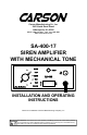
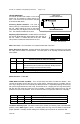
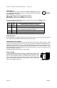
Carson Manufacturing Co., Inc. 5451 North Rural Street Indianapolis, IN 46220 Phone: (888) 577-6877 Fax: (317) 254-2667 www.carsonsirens.com SA-400-17 SIREN AMPLIFIER WITH MECHANICAL TONE RADIO SIREN STBY MECH PA VOL SA-400 WAIL YELP PHASER O F F O N INSTALLATION AND OPERATING INSTRUCTIONS Carson is a trademark of Carson Manufacturing Company, Inc. Sound Hazard - Sound level from siren speaker (>120dBA @ 10 feet) may cause hearing damage.
Page 2 of 12 SA-400-17 Installation and Operating Instructions TABLE OF CONTENTS GENERAL DESCRIPTION .................................................................................... 3 SPECIFICATIONS................................................................................................. 3 INSTALLATION ..................................................................................................... 4 SAFETY PRECAUTIONS ........................................................................
SA-400-17 Installation and Operating Instructions Page 3 of 12 GENERAL DESCRIPTION The SA-400 Siren Amplifier with Mechanical Tone is a premium unit designed for single or dual 100W speaker use. A 6-position rotary selector switch controls the primary operating modes of Radio, Standby, Mechanical, Wail, Yelp, and Phaser. Two-Tone may optionally replace Phaser.
Page 4 of 12 SA-400-17 Installation and Operating Instructions INSTALLATION Proper installation of the unit is essential for years of safe, reliable operation. Please read all instruction before installing the unit. Failure to follow these instructions can cause serious damage to the unit or vehicle and may void warranties. SAFETY PRECAUTIONS For the safety of the installer, vehicle operator, passengers and the community please observe the following safety precautions.
SA-400-17 Installation and Operating Instructions Page 5 of 12 OPTION SWITCHES An internal 8-position DIP switch on the circuit board may be changed to select various options. The cover for the unit must be removed to access the DIP switch. Accessing Option Switches - The cover is held in place by a snap-fastener on the back of the unit. While holding the cover on the sides press hard with your fingers on the back of the unit. The chassis will slide out the front.
Page 6 of 12 SA-400-17 Installation and Operating Instructions MOUNTING The mounting bracket supplied can be installed above or below the unit. Choose a mounting location convenient to the operator and away from any air bag deployment areas. Inspect behind mounting area for clearance. Assure adequate ventilation to prevent overheating. Consider wire routing and access to connections, as well as microphone bracket placement. Install mounting bracket to vehicle using 1/4" hardware (not supplied).
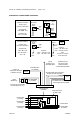
SA-400-17 Installation and Operating Instructions Page 7 of 12 ELECTRICAL CONNECTIONS CONTINUED Traditional Activation Auxiliary Input Connection Examples HORN RLY Momentary SPST Switch +VDC or -VDC Activated with +VDC AND -VDC DIP SW-6 ON SW-7 and 8 OFF To AUX Polarized Activation Auxiliary Input Connection Examples DIP SW-6 OFF SW-7 ON To AUX Added SPDT Switch To AUX Vehicle Horn Horn Circuit Momentary SPST Switch Activated with +VDC OR -VDC +VDC or -VDC +VDC or -VDC Splice Activation
Page 8 of 12 SA-400-17 Installation and Operating Instructions OPERATION Sound Hazard - Sound level from siren speaker (>120dBA @ 10 feet) may cause hearing damage. Do not operate siren without adequate hearing protection for you and anyone in immediate vicinity. (Ref. OSHA 1910.95 for occupational noise exposure guidelines) GENERAL This unit is designed for easy operation under the stress associated with high-speed pursuit.
SA-400-17 Installation and Operating Instructions Page 9 of 12 SIREN SWITCH This momentary push-button switch provides Horn or Manual tone control. It can optionally control Horn Ring Cycler 2 operation in the Standby position if the HRC2 option is selected. Horn - A simulated Air-horn tone momentarily sounded. Manual Wail - Manual control of Wail tone rise and fall. Manual Mech - Manual control of Mech tone rise and fall.
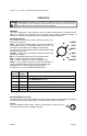
Page 10 of 12 SA-400-17 Installation and Operating Instructions SERVICE This unit is designed to provide years of reliable service under even the worst conditions. Many times there may appear to be a problem with the unit when the true problem is in the speaker(s) or improper installation. The following chart shows typical symptoms and possible causes. A blown rear panel fuse doesn't necessarily mean that the unit is bad.
SA-400-17 Installation and Operating Instructions Page 11 of 12 PARTS and ACCESSORIES The following parts and accessories are available from Carson Manufacturing Company, Inc.
Page 12 of 12 SA-400-17 Installation and Operating Instructions RETURN If you have any questions concerning this or any other Carson product, please contact our Technical Service Department at (888) 577-6877. Many issues can be handled over the phone. We can also be reached via e-mail at service@carsonsirens.com If a product must be returned for any reason, please contact our Technical Service Department to obtain a Returned Merchandise Authorization number (RMA#) before you ship the product to Carson.