Carson MANUFACTURING COMPANY, INC. SA-430 REMOTE SIREN AMPLIFIER RADIO MAN W AIL YELP PA VOL SIREN HORN Carson ON POWER PHASER SASA-430 INSTALLATION AND OPERATING INSTRUCTIONS 5451 N. Rural Street Indianapolis, IN 46220 Phone: (888) 577-6877 Fax: (317) 254-2667 Website: www.carsonsirens.
Page 2 SA-430 Installation and Operating Instructions TABLE OF CONTENTS SPECIFICATIONS ................................................................................................................... 3 NOTICE.................................................................................................................................... 3 GENERAL DESCRIPTION....................................................................................................... 4 INSTALLATION...........................
SA-430 Installation and Operating Instructions Page 3 SPECIFICATIONS Input Voltage Input Current 11 - 16 VDC (negative ground) 8 AMPS (@14.0 VDC - single 100W speaker) 16 AMPS (@14.0 VDC - dual 100W speakers) Standby Current Less than 250 mA Audio Frequency 200Hz - 10 kHz + 3db Audio Distortion Less than 3% (@1 kHz - single 100W speaker) Audio Output 40 watts (@14.0 VDC - single 100W speaker) Audio Input 400 ohms + 10% Output Power 105 WATTS RMS MAX. (15.0 VDC - single 100W speaker) 180 WATTS RMS MAX.
Page 4 SA-430 Installation and Operating Instructions GENERAL DESCRIPTION The SA-430 Siren Amplifier is a premium unit designed for single or dual 100W speaker use from a 12 volt DC power source (negative ground). The control head is only 1 inch deep and can be installed in minimum clearance areas. Connection between the control head and amplifier is via a single lead wire with common ground. A 6-position rotary switch controls the primary operating modes of Phaser, Yelp, Wail, Manual, Horn and Radio.
SA-430 Installation and Operating Instructions Page 5 INSTALLATION Proper installation of the unit is essential for years of safe, reliable operation. Please read all instruction before installing the unit. Failure to follow these instructions can cause serious damage to the unit or vehicle and may void warranties. SAFETY PRECAUTIONS For the safety of the installer, vehicle operator, passengers and the community please observe the following safety precautions.
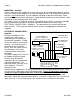
Page 6 SA-430 Installation and Operating Instructions OPTION SWITCHES Various options can be controlled by turning on or off any of 8 DIP switches exposed in the amplifier. Switch 1 On: Two-Tone - Two-Tone replaces Phaser function. Switches 1 & 2 On: Phaser Disable - The Phaser function is disabled. Switch 3 On: Horn Disable - The Horn function is disabled.
SA-430 Installation and Operating Instructions Page 7 When connected to the red lead, make sure that the ignition switch controls the power to that connection. This prevents the panel lights from being continuously on. White: Control - Connect white leads from amplifier and control head. The connection may be extended with any size wire. Route this lead away from the transmitter antenna lead to prevent R.F. interference being fed to the siren amplifier. Green: Auxiliary Input - Used for Siren control.
Page 8 SA-430 Installation and Operating Instructions MOUNTING – Amplifier Select a location for the amplifier in an area such as the driver compartment firewall, under a seat, etc. Mounting the amplifier in the engine compartment or in an area directly exposed to weather is not recommended. Assure adequate ventilation to prevent overheating. Allow clearance for wiring and radio adjustment. Inspect behind mounting area for clearance. Mark the location of the mounting holes to be drilled.
SA-430 Installation and Operating Instructions Cutout Input Connection - The Cutout Input turns off any siren tone output when activated, and remains off until a control is activated or changed. The adjacent diagram shows two connection examples. See the INSTALLER-SELECTABLE OPTIONS section for programming details.
Page 10 SA-430 Installation and Operating Instructions OPERATION GENERAL This unit is designed for easy operation under the stress associated with high-speed pursuit. Most siren functions are accessible with one simple motion without repetitive activation of switches or automatic timed switching that can interfere with desired operation. SELECTOR SWITCH The 6-position rotary selector switch controls the primary operating function of the siren.
SA-430 Installation and Operating Instructions Page 11 RADIO VOLUME The radio repeat volume level is set using an adjustment on the side of the amplifier. Set the Selector Switch to the Radio position and turn on the power. With the radio volume set to normal level, adjust the siren radio repeat control to the desired level. OVERRIDE FUNCTIONS In addition to PA Override, two other override functions are available and controlled by the Siren button or auxiliary input.
Page 12 SA-430 Installation and Operating Instructions SERVICE This unit is designed to provide years of reliable service under even the worst conditions. Many times there may appear to be a problem with the unit when the true problem is in the speaker(s) or improper installation. The following chart shows typical symptoms and possible causes. A blown rear panel fuse doesn't necessarily mean that the unit is bad. If a speaker or speaker lead is shorted this fuse will blow before the unit is damaged.
SA-430 Installation and Operating Instructions Page 13 PARTS The following parts are available from Carson Manufacturing Company, Inc.
Page 14 SA-430 Installation and Operating Instructions LIMITED WARRANTY Carson Manufacturing Company, Inc. warrants this new product to be free from defects in material and workmanship, under normal use and service, for a period of five (5) years from the date of delivery to the first user-purchaser.
03/22/02 2-7/8” 2-1/2” CAUTION: Please note that top and bottom edges only provide 1/8” overlap. Cut carefully. This inner area to be removed.