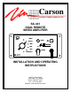
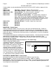
Carson MANUFACTURING COMPANY, INC. SA-441 DUAL REMOTE SIREN AMPLIFIER O F F O N DUAL RADIO MAN WAIL YELP PA V OL SIREN HRN/TT Carson ON POWER PHASR/WPHASR/W- Y SASA-441 INSTALLATION AND OPERATING INSTRUCTIONS 5451 N. Rural Street Indianapolis, IN 46220 Phone: (888) 577-6877 Fax: (317) 254-2667 Website: www.carsonsirens.
Page 2 SA-441 Installation and Operating Instructions TABLE OF CONTENTS TABLE OF CONTENTS ........................................................................................................... 2 SPECIFICATIONS ................................................................................................................... 3 NOTICE.................................................................................................................................... 3 GENERAL DESCRIPTION.................
SA-441 Installation and Operating Instructions Page 3 SPECIFICATIONS Input Voltage Input Current Standby Current Audio Frequency Audio Distortion Audio Output Audio Input Output Power Siren Frequency Tones / Cycle Rates 11 - 16 VDC (negative ground) 17 AMPS (@14.0 VDC - dual 100W speakers) Less than 250 mA 200Hz - 10 kHz + 3db Less than 3% (@1 kHz - dual 100W speaker) 80 watts (@14.0 VDC - dual 100W speaker) 400 ohms + 10% 210 WATTS RMS MAX. (15.
Page 4 SA-441 Installation and Operating Instructions GENERAL DESCRIPTION The SA-441 Dual Siren Amplifier is a premium unit designed for dual 100W speaker use from a 12 volt DC power source (negative ground). The control head is only 1 inch deep and can be installed in minimum clearance areas. Connection between the control head and amplifier is via a single lead wire with common ground. A 6-position rotary switch controls the primary operating modes of Phaser, Yelp, Wail, Manual, Horn and Radio.
SA-441 Installation and Operating Instructions Page 5 INSTALLATION Proper installation of the unit is essential for years of safe, reliable operation. Please read all instruction before installing the unit. Failure to follow these instructions can cause serious damage to the unit or vehicle and may void warranties. SAFETY PRECAUTIONS For the safety of the installer, vehicle operator, passengers and the community please observe the following safety precautions.
Page 6 SA-441 Installation and Operating Instructions OPTION SWITCHES Various options can be controlled by turning on or off any of 8 DIP switches exposed in the amplifier. Switch 1 On: Two-Tone - Two-Tone replaces Phaser function. Switch 2 On: Dual Phaser Disable – Provides single Phaser signal only. Switches 1 & 2 On: Phaser Disable - The Phaser function is disabled. Switch 3 On: Horn Disable - The Horn function is disabled.
SA-441 Installation and Operating Instructions Page 7 Yellow: Lights - This lead may be connected to the dash lights or to the red power lead. Connecting to the dash lights will turn on the panel lights whenever the dash lights are on. When connected to the red lead, make sure that the ignition switch controls the power to that connection. This prevents the panel lights from being continuously on. White: Control - Connect white leads from amplifier and control head.
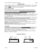
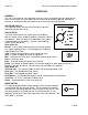
Page 8 SA-441 Installation and Operating Instructions SPKR Aà SPK COMà POSà POSà RADà RADà CTRLà SPKR Bà NEGà NEGà MOUNTING – Amplifier Select a location for the amplifier in an area such as the driver compartment firewall, under a seat, etc. Mounting the amplifier in the engine compartment or in an area directly exposed to weather is not recommended. Assure adequate ventilation to prevent overheating. Allow clearance for wiring and radio adjustment. Inspect behind mounting area for clearance.
SA-441 Installation and Operating Instructions Page 9 SIREN TESTING Before re-connecting the battery in the vehicle make sure that the siren is turned off. Observe polarity when re-connecting. Caution: Hearing protection should always be used when testing any siren, especially indoors. The sound levels produced by the speakers may cause hearing loss. The following procedure should be used to test the siren: 1.
Page 10 SA-441 Installation and Operating Instructions OPERATION GENERAL This unit is designed for easy operation under the stress associated with high-speed pursuit. Most siren functions are accessible with one simple motion without repetitive activation of switches or automatic timed switching that can interfere with desired operation. SELECTOR SWITCH The 6-position rotary selector switch controls the primary operating function of the siren.
SA-441 Installation and Operating Instructions Page 11 MICROPHONE (PA Override) The attached noise-canceling microphone is used for public address operation and overrides any function when the button on the side is pressed. PA VOL This control adjusts the PA volume. With the vehicle parked, set the PA volume to the maximum level with no feedback (squeal). PA VOL AUXILIARY INPUT During installation an auxiliary input may be connected to the horn ring or other switching device.
Page 12 SA-441 Installation and Operating Instructions SERVICE This unit is designed to provide years of reliable service under even the worst conditions. Many times there may appear to be a problem with the unit when the true problem is in the speaker(s) or improper installation. The following chart shows typical symptoms and possible causes. A blown rear panel fuse doesn't necessarily mean that the unit is bad. If a speaker or speaker lead is shorted this fuse will blow before the unit is damaged.
SA-441 Installation and Operating Instructions Page 13 PARTS The following parts are available from Carson Manufacturing Company, Inc.
Page 14 SA-441 Installation and Operating Instructions LIMITED WARRANTY Carson Manufacturing Company, Inc. warrants this new product to be free from defects in material and workmanship, under normal use and service, for a period of five (5) years from the date of delivery to the first user-purchaser.
11/6/01 2-7/8” 2-1/2” CAUTION: Please note that top and bottom edges only provide 1/8” overlap. Cut carefully. This inner area to be removed.