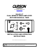
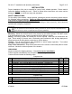
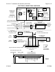
Carson Manufacturing Co., Inc. 5451 North Rural Street Indianapolis, IN 46220 Phone: (888) 577-6877 Fax: (317) 254-2667 www.carsonsirens.com SA-441-17 DUAL REMOTE SIREN AMPLIFIER WITH MECHANICAL TONE O F F O N DUAL RADIO SIREN STBY MECH WAIL YELP ON PA VOL SA-441 POWER PHASER INSTALLATION AND OPERATING INSTRUCTIONS Carson is a trademark of Carson Manufacturing Company, Inc. Sound Hazard - Sound level from siren speaker (>120dBA @ 10 feet) may cause hearing damage.
Page 2 of 15 SA-441-17 Installation and Operating Instructions TABLE OF CONTENTS TABLE OF CONTENTS ............................................................................................................. 2 SPECIFICATIONS ..................................................................................................................... 3 NOTICE .....................................................................................................................................
SA-441-17 Installation and Operating Instructions Page 3 of 15 SPECIFICATIONS Input Voltage Input Current Standby Current Audio Frequency Audio Distortion Audio Output Audio Input Output Power Siren Frequency 11 - 16 VDC (negative ground) 17 AMPS (@14 VDC - dual 100W speakers) Less than 250 mA 200Hz - 10 kHz + 3db Less than 3% (@1 kHz - dual 100W speaker) 80 watts (@14 VDC - dual 100W speaker) 400 ohms + 10% 210 WATTS RMS MAX.
Page 4 of 15 SA-441-17 Installation and Operating Instructions GENERAL DESCRIPTION The SA-441 Dual Siren Amplifier with Mechanical Tone is a premium unit designed for dual 100W speaker use. The control head is only 1 inch deep and can be installed in minimum clearance areas. Connection between the control head and amplifier is via a single lead wire with common ground. A 6-position rotary selector switch controls the primary operating modes of Radio, Standby, Mechanical, Wail, Yelp, and Phaser.
SA-441-17 Installation and Operating Instructions Page 5 of 15 INSTALLATION Proper installation of the unit is essential for years of safe, reliable operation. Please read all instruction before installing the unit. Failure to follow these instructions can cause serious damage to the unit or vehicle and may void warranties. SAFETY PRECAUTIONS For the safety of the installer, vehicle operator, passengers and the community please observe the following safety precautions.
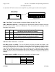
Page 6 of 15 SA-441-17 Installation and Operating Instructions OPTION SWITCHES An 8-position DIP switch on the remote amplifier may be changed to select various options. Option Switches On Remote Amp ON 8 7 6 5 4 3 2 1 Option Switches Default Setting (Shown) all OFF (UP) SW-1 Two-Tone - Turn this switch on to replace Phaser tone with Two-Tone. SW-2 Mechanical Override - Pressing the Siren push-button normally produces Horn tone while the rotary function switch is in Mechanical.
SA-441-17 Installation and Operating Instructions Page 7 of 15 MOUNTING – Amplifier Select a location for the amplifier in an area such as the driver compartment firewall, under a seat, etc. Mounting the amplifier in the engine compartment or in an area directly exposed to weather is not recommended. Assure adequate ventilation to prevent overheating. Allow clearance for wiring and radio adjustment. Inspect behind mounting area for clearance. Mark the location of the mounting holes to be drilled.
Page 8 of 15 SA-441-17 Installation and Operating Instructions ELECTRICAL CONNECTIONS - Amplifier Electrical connections to the amplifier are made using a terminal block plug located on the amplifier. A label on the unit identifies each terminal function. You should install the plug on the unit before wiring. If the unit needs service the plug can be easily removed without unwiring.
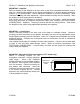
SA-441-17 Installation and Operating Instructions Page 9 of 15 ELECTRICAL CONNECTIONS CONTINUED Momentary SPST Switch Auxiliary Input Connection Examples Aux input is activated with +VDC AND -VDC HORN RLY +VDC or -VDC To AUX Control Head Cable may be extended with #22AWG Wire Backlighting Control Line to Amplifier -VDC Customer Fused +VDC Connect to output jack, terminals or speaker of radio 100W Speaker 100W Speaker +VDC or -VDC Vehicle Horn (AUX) Auxiliary Input Yellow Wire White Wire Black Wir
Page 10 of 15 SA-441-17 Installation and Operating Instructions OPERATION Sound Hazard - Sound level from siren speaker (>120dBA @ 10 feet) may cause hearing damage. Do not operate siren without adequate hearing protection for you and anyone in immediate vicinity. (Ref. OSHA 1910.95 for occupational noise exposure guidelines) GENERAL This unit is designed for easy operation under the stress associated with high-speed pursuit.
SA-441-17 Installation and Operating Instructions Page 11 of 15 SIREN SWITCH This momentary push-button switch provides Horn or Manual tone control. It can optionally control Horn Ring Cycler 2 operation in the Standby position if the HRC2 option is selected. Horn - A simulated Air-horn tone momentarily sounded. Manual Wail - Manual control of Wail tone rise and fall. Manual Mech - Manual control of Mech tone rise and fall.
Page 12 of 15 SA-441-17 Installation and Operating Instructions SERVICE This unit is designed to provide years of reliable service under even the worst conditions. Many times there may appear to be a problem with the unit when the true problem is in the speaker(s) or improper installation. The following chart shows typical symptoms and possible causes. A blown amplifier fuse doesn't necessarily mean that the unit is bad.
SA-441-17 Installation and Operating Instructions Page 13 of 15 PARTS and ACCESSORIES The following parts and accessories are available from Carson Manufacturing Company, Inc.
Page 14 of 15 SA-441-17 Installation and Operating Instructions RETURN If you have any questions concerning this or any other Carson product, please contact our Technical Service Department at (888) 577-6877. Many issues can be handled over the phone. We can also be reached via e-mail at service@carsonsirens.com If a product must be returned for any reason, please contact our Technical Service Department to obtain a Returned Merchandise Authorization number (RMA#) before you ship the product to Carson.
07/29/08 2-7/8” 2-1/2” CAUTION: Please note that top and bottom edges only provide 1/8” overlap. Cut carefully. This inner area to be removed.