Carson Manufacturing Co., Inc. 5451 North Rural Street Indianapolis, IN 46220 Phone: (888) 577-6877 Fax: (317) 254-2667 www.carsonsirens.
Page 2 of 12 SC-1002/1012-10 Installation Instructions TABLE OF CONTENTS GENERAL DESCRIPTION ....................................................................................3 SPECIFICATIONS .................................................................................................3 INSTALLATION .....................................................................................................4 SAFETY PRECAUTIONS .................................................................................
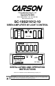
SC-1002/1012-10 Installation Instructions Page 3 of 12 GENERAL DESCRIPTION The SC-1002/1012 Siren Amplifier with Light Control is designed for single 100W speaker use. The primary operating modes are Mechanical, Wail, Yelp, and Standby, selected by 3-position rocker switches. Momentary Horn Override, Momentary Phaser Override or push-on/push-off Phaser operation while in the Mechanical, Wail, and Yelp modes. Manual siren control of Mechanical, Wail, and Yelp.
Page 4 of 12 SC-1002/1012-10 Installation Instructions INSTALLATION Proper installation of the unit is essential for years of safe, reliable operation. Please read all instruction before installing the unit. Failure to follow these instructions can cause serious damage to the unit or vehicle and may void warranties. SAFETY PRECAUTIONS For the safety of the installer, vehicle operator, passengers and the community please observe the following safety precautions.
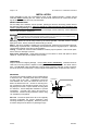
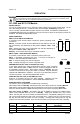
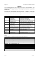
SC-1002/1012-10 Installation Instructions Page 5 of 12 OPTION SWITCHES An internal 8-position DIP switch on the circuit board may be changed to select various options. Accessing Option Switches - the DIP switch is located just behind the front panel of the amplifier. Use a 7/64” allen wrench to remove the 4 corner screws and front panel. SW-1 (AUX_P) Auxiliary Input Polarity - The auxiliary input is normally activated with positive. Turn switch off for negative activation.
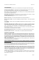
Page 6 of 12 SC-1002/1012-10 Installation Instructions ELECTRICAL CONNECTIONS (ALL MODELS) +VDC HORN RING SWITCH +VDC HORN RING SWITCH SPLICE Added SPDT Switch MOMENTARY FOOT SWITCH HORN AUX HORN -VDC switching example AUX AUX Must set AUX_P option switch +VDC Switching examples Load 1 and Load 2 Recommended Wire Size Amps Size 5 - 10 #16 10 - 15 #14 15 - 20 #12 #22 AWG WHT Load 1 #22 AWG ORG Unit Enable (like an ON/OFF switch) Connect to positive circuit (fuse panel) controlled by
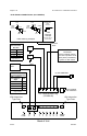
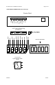
SC-1002/1012-10 Installation Instructions Page 7 of 12 ELECTRICAL CONNECTIONS (SC-1012 only) Front of Unit REMOTE PANEL LT2 LT1 HORN PHSR MECH YELP MAN AUTO LAMP NEG 10-P Terminal Block Plug (CP4688-10) Plug installed this orientation NEG AUTO MAN YELP MECH HORN PHSR LT1 LAMP LT2 LAMP Note Top Orientation SC-1012 MAN MECH PHSR YELP HORN LT1 LT2 W A I L S T B Y AUTO LT1 and LT2 Lighted Rocker Switch Circuit CP4997A 3/27/07
Page 8 of 12 SC-1002/1012-10 Installation Instructions OPERATION Sound Hazard - Sound level from siren speaker (>120dBA @ 10 feet) may cause hearing damage. Do not operate siren without adequate hearing protection for you and anyone in immediate vicinity. (Ref. OSHA 1910.95 for occupational noise exposure guidelines) SC-1002 and SC-1012 Models POWER ON/OFF The unit is enabled (turned on) by applying positive voltage to the orange enable lead. On the SC-1002, backlight turns on.
SC-1002/1012-10 Installation Instructions Page 9 of 12 OPERATION (SC-1002 and SC-1012 Models continued) LIGHT CONTROLS LIGHTED ROCKER SWITCHES LT1 and LT2 When turned on the rocker switch will light up and activate the corresponding light output.
Page 10 of 12 SC-1002/1012-10 Installation Instructions SERVICE This unit is designed to provide years of reliable service under even the worst conditions. Many times there may appear to be a problem with the unit when the true problem is in the speaker, controlled devices, or improper installation. The following chart shows typical symptoms and possible causes. A blown siren fuse doesn't necessarily mean that the unit is bad.
SC-1002/1012-10 Installation Instructions Page 11 of 12 RETURNS If you have any questions concerning this or any other Carson product, please contact our Technical Service Department at (888) 577-6877. Many issues can be handled over the phone. We can also be reached via e-mail at service@carsonsirens.com If a product must be returned for any reason, please contact our Technical Service Department to obtain a Returned Merchandise Authorization number (RMA#) before you ship the product to Carson.
Page 12 of 12 SC-1002/1012-10 Installation Instructions BLANK PAGE 3/27/07 CP4997A