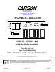
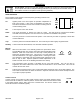
Carson Manufacturing Co., Inc. 5451 North Rural Street Indianapolis, IN 46220 Phone: (888) 577-6877 Fax: (317) 254-2667 www.carsonsirens.com TECHNICAL BULLETIN SC-407 YELP STBY W AIL ON OFF RAD MAN/PHSR L ALY OFF 1 2 HORN R ALY VOLUME RAD PA AUX 1 AUX 2 3 INSTALLATION AND OPERATING MANUAL SC-407-10 14V (OLD VERSION) Different Auxiliary and Cutout Input Polarity Options Carson is a trademark of Carson Manufacturing Company, Inc.
SC-407-10 AMPLIFIER INPUT POWER: SIREN MODE OUTPUT POWER: AUDIO MODE OUTPUT POWER: SIREN FREQUENCY: CYCLE RATES: AUDIO RESPONSE: SPECIFICATIONS 9-16 Volts DC, 8 Amps DC per 100W Speaker 15 VDC input, 100W speaker(s) One speaker – 105 Watts RMS Two speakers - 180 Watts RMS 14 VDC input, 100W speaker(s) One speaker – 40 Watts RMS Two speakers - 80 Watts RMS 700Hz - 1450Hz Nominal WAIL - 15 cycles/min YELP - 210 cycles/min PHASER - 15 cycle/sec TWO-TONE – 1 cycle/min 200Hz - 10KHz +/-3db Harmonic Distortion
INSTALLATION Proper installation of the unit is essential for years of safe, reliable operation. Please read all instruction before installing the unit. Failure to follow these instructions can cause serious damage to the unit or vehicle and may void warranties. SAFETY PRECAUTIONS For the safety of the installer, vehicle operator, passengers and the community please observe the following safety precautions.
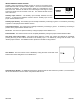
FUSE Auxiliary Input Function - The auxiliary input normally activates the Horn function. To activate the Man/Phsr function with the auxiliary input cut the jumper resistor labeled "AUX I". T-T AUX P CUT P PHSR AUX I INSTALLER-SELECTABLE OPTIONS Carefully cutting programming resistor jumpers or traces on the printed circuit board inside the case can select various options. The cover must be removed to access the jumpers. The cover is held in place by a snap-fastener on the back of the unit.
ELECTRICAL CONNECTIONS Disconnect vehicle battery before making any electrical connections. Make electrical connections with supplied terminal block plug for siren functions and spliced lead wires for light control outputs. Wiring is not supplied. Wire Size and Termination - The diagram shows the minimum wire size used for each connection, along with recommended lead color. If the wire is longer than 10 ft. use the next larger wire size.
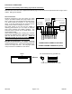
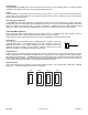
+VDC HORN RING SWITCH +VDC SPLIC E Added SPDT Switc h HORN RING SWITCH HORN MOMENTARY FOOT SWITCH AUX HORN AUX (Add re sistor to GND) AUX +VDC Switching examples -VDC switching example Must cut AUX P option resistor Added r esistor to GND 1K @ 1/4 watt •••••••••• SPKR SPKR POS POS RAD RAD AUX CUT NEG NEG → → → → → → → → → → Auxiliary Input Connection - The Auxiliary Input allows activation by an external source of either the Horn or Man/Phsr function.
Light Control Connections In addition to these instructions a label located on the bottom of the unit shows the light control switch connections. Fuses / Breakers The lighting control circuits of this unit are not fused. Automotive fuses or circuit breakers must be connected between the power source and the unit properly rated for the circuit requirements. Failure to install proper circuit breakers or fuses can result in damage to the unit and/or vehicle.
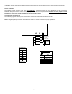
Light Control Rocker Switch Connections The following diagram shows proper connection of the rocker switch leads located at the rear. Note: Negative (NEG) connection must also be made on 10-Pin connector for rocker switches to light up. WARNING: The lighting control circuits of this unit are not fused. Automotive fuses or circuit breakers must be connected between the power source and the unit properly rated for the circuit requirements.
OPERATION Sound Hazard - Sound level from siren speaker (>120dBA @ 10 feet) may cause hearing damage. Do not operate siren without adequate hearing protection for you and anyone in immediate vicinity. (Ref. OSHA 1910.95 for occupational noise exposure guidelines) SIREN CONTROLS Two 3-position rocker switches control the primary operating modes of siren. These modes are as follows: YELP STBY WAIL ON OFF RAD On: Applies power to the siren system for operation independent of light control system.
Auxiliary Input During installation an auxiliary input may be connected to the horn ring or other switching device. It provides the same operation as pressing the Horn button or optionally the Man/Phsr button. Cutout During installation a cutout input may be connected to a door switch. It turns off any siren tone when the door is opened. The siren tone will continue to be cut off even when the door is closed. Changing any siren control switch or input will restore normal function.
SERVICE This unit is designed to provide years of reliable service under even the worst conditions. Many times there may appear to be a problem with the unit when the true problem is in the speaker(s), controlled devices, or improper installation. The following chart shows typical symptoms and possible causes. A blown internal siren fuse doesn't necessarily mean that the unit is bad. If a speaker or speaker lead is shorted this fuse will blow before the unit is damaged.
RETURN If you have any questions concerning this or any other Carson product, please contact our Technical Service Department at (888) 577-6877. Many issues can be handled over the phone. We can also be reached via e-mail at service@carsonsirens.com If a product must be returned for any reason, please contact our Technical Service Department to obtain a Returned Merchandise Authorization number (RMA#) before you ship the product to Carson. Please write the RMA# clearly on the package near the mailing label.