
User's Manual


Sybox manual (AI-02.02)
Page 4 of 7
Page 4 of 7
B. Installation
The twisted pair cable with the male DB15 connector comes out of the carrier.
All signals are available at the four DB9 socket connectors Opto-J1 .. Opto-J4. Each connector
offers all four signals. They all have the same pin assignments.
plug in the DB15 connector into the Sybox connector marked “TransPC”
connect one to four connectors from your electronic interfaces to the Opto-J1 .. Opto-
J4 connectors
Details for connecting your computer or your system
One of your connectors must have the power supply at pin 1
(5V, 50mA) and at pin 6 (ground).
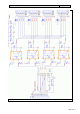
Please refer to the schematic in fig.6 for more details. The
power supply is necessary to provide the opto couplers output
stage with the required 5 V.
The pins marked “internal*” have a connection to a free solder
point. This is for bringing signals from your electronic into
additional logic inside the Sybox (see Extensions).
Please ask bahne@articulograph.de if you have problems to
provide the power supply.
Pin
Signal
1
5V Power supply
2
PSR_dn
3
Attention
4
Sweep
5
T_active
6
ground
7
internal*
8
internal*
9
internal*
Table 1: Opto-J# connections