
User's Manual


AG501 cs5cal (PD-02.05)
Page 9 of 11
7. Check the calibration result
The important information that is needed in order to review the calibration results is in the calibration
protocol file (*.txt) inside the calibration set sub folder.
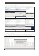
a) An Example calibration protocol file:
To get a better overview, the data of channels 2 to 15 is omitted.
Calibration protocol
Given name is: test-1
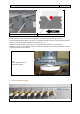
Moving circal ..
Circal ready.
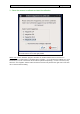
Creating calset: /data/calibration/test-1.calset
Circal ready.
Moving circal ..
Circal ready.
Result : Done successfully.
__channel1_phase 0.17238 -179.22888 -179.43175 -179.20283 0.52733 5.01513 -179.45138 -179.00359 179.80718
__channel16_phase 0.29336 0.64651 0.67383 0.09369 0.45454 4.67573 -179.50294 0.83442 1.18688
__channel1_calibration_factors -2007.80 2426.34 -2656.46 2229.63 2509.71 -2706.69 -2282.96 2512.43 2738.64
__channel16_calibration_factors -2020.07 2443.39 -2673.06 2243.29 2525.56 -2723.57 -2296.59 2530.02 2754.23
__channel1_a0_r_z_phi_theta_rms -0.38 80.165 42.155 45.841 3.130 8.817
__channel16_a0_r_z_phi_theta_rms -0.22 80.225 42.045 48.829 -2.027 8.139
mean RMS max RMS mean z delta z stddev z
__channel1_circal_run 4.71 9.58 41.51 0.71 0.15
__channel12_circal_run 4.36 13.00 41.56 0.93 0.17
StdDev_Angle_max 0.16531
StdDev_Angle_mean 0.08533
StdDev_Position_max 0.33843
StdDev_Position_mean 0.24572
b) calibration quality
The line for each channel shows the parameters a0, r, z, phi, theta, and rms arranged from left to
right.
a0 = alpha0 - the deviation from the expected zero position for this sensor on the Circal disk
r = the Radius described by this sensor during a Circal revolution (=80mm)
z = the averaged z – coordinate from this sensor during a Circal revolution
phi = the angle between the sensor's axis and a line to the circal's centre (=45°).
theta= the angle between the sensor's axis and the xy plane (elevation = 0°).
The value for a0 should be less than +0.5°. If it is not, please check the "Circal Logic Zero position" in
the "setup_circal.pdf" document.
The r, z, phi, and theta values depend on the Circal parameter. The parameters have a fix ideal value
that can vary depending on the positioning of the sensor inside the magazine.
c) Circal run
The "delta z" shows the peak to peak deviation of the z-coordinates from each channel – during the
Circal run. This is one criterion for the calibration quality (the smaller the better). In an ideal error free
system, the delta z would be 0. The stddev Z should be less than 0.25 mm. The Circal run is stored in
the following directory: /data/calibration/test-1/TMP00000.tmp/tests/rawpos/0001.pos. You will be able
to display this data with Cs5view
d) Deviation summary
There are four lines showing the maximum and mean deviation in the Circal run and all extra
recordings
The first line shows the maximum deviation that occurred between any two sensor axes.
The second line shows the mean of all measured changes of angle differences.
The third line shows the maximum deviation that occurred in the Euclidian distance between any two
sensors.
The fourth line shows the mean of all measured changes of the Euclidian distance differences.
To get a more detailed analysis of the above differences, please find the file in the following directory:
/data/calibration/test-1/TMP00000.tmp/tests/rawpos/distmatrix.txt.
calibration quality
RMS
calibration quality
stddevZ
Deviation
summary
calibration factors